A - Scan Path
The Adjust Filter construction type lets you adjust scan data that was gathered while scanning around these standard geometric features:
Sphere
Cone
Cylinder
Generally, you perform these scans using an analog probe, such as an SP600. If you imagine a scan around the top quarter of a sphere, for example, you would ideally get points that lie within a plane that cuts through the sphere, like this:

A - Scan Path
However, in reality, as the probe scans around the sphere, it is physically impossible for all the points to remain inside the cut plane due to a natural rise and fall floating motion of the CMM.
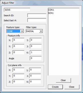
The Adjust Filter construction can take the pre-existing scanned points and, using the known mathematical properties of the feature, better compensate the points gathered during the measurement process, adjusting them to lie more within the cut plane. You use the Adjust filter dialog box to do this. To access this dialog box, select Insert | Feature | Constructed | Adjust Filter.

Adjust filter dialog box
The dialog has these options:
Feature
Type
This defines the primitive (simple geometric feature) being scanned. You
can only select Sphere, Cone,
or Cylinder.
Filter
Type
This defines the type of filter to use, either Axial
or Radial (applies to Cone and Cylinder feature
only - see step 4 below).
Feature
Info
This lets you define the information about the feature.
XYZ
- The feature's nominal position.
IJK - The feature's normal vector.
Radius/Angle - This sets the Radius of the Sphere
or Cylinder or the angle of the Cone.
Cut Plane
Info
This area defines the location and vector of the cut plane.
XYZ
- Location of the Cut Plane
IJK - Vector of the Cut Plane
To Adjust Scan Data
To correctly adjust the data in the scan, you need to give enough information to mathematically define the feature.
Select the actual sphere, cone, or cylinder feature from the list of features in the Adjust filter dialog box.
Select a pre-existing scan feature from the list. Generally, your scanned feature is a pre-existing linear closed scan. The scan must be of a sphere, cone, or cylinder.
Choose the feature type you scanned with the selected scan from the Feature Type list.
From the Filter Type list, choose the correct filter type for a Cone or Cylinder feature. The filter indicates how to compensate the data.
If you are scanning perpendicular to the axis of the Cylinder or Cone, choose the Radial filter. This defines the circle that is used to adjust the points.
If you are scanning parallel to the feature's axis, choose the Axial filter. This defines a line that is used to adjust the points.
Define the feature's nominal XYZ location by typing the values in the XYZ boxes.
Define the feature's normal vector by typing the values in the IJK boxes.
Define the feature's size by typing a value in the Radius or Angle box.
In the Cut Plane Info area, define the scan's cut plane. Once you specify all the nominal information for the scanned feature, you can create the construction.
Click Create. All the points are projected into the cut plane along the features theoretical definition (taking into account the known geometry) rather than a straight projection along the features normal vector.