In this Topic Hide
A flatness specification controls how much the feature can deviate from being perfectly flat. In other words, flatness evaluates how flat the feature is. PC-DMIS only supports flatness specifications on planes.
Actual Value:
This is the minimum distance between two parallel planes that contain the
entire surface between them.
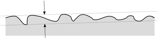
Measured Value:
This is the distance between two parallel planes that contain all the measured
points between them. A best-fitting routine determines the surface normal
of the two planes. Depending on the measurement uncertainty, how many
points you measured, and where you took the points, this can be larger
or smaller than the actual value. Here's an illustrated case where too
few points were measured, so the measured value is smaller than the actual
value:

You can use planar features that have surface data. For details on planes that have surface data, refer to "Feature Types With and Without Surface Data".
None. This geometric tolerance does not allow modifiers.
Exposed Options
The tolerance zone math type controls the best fitting routine:
DEFAULT - This computes a minimum-zone best fit plane (also called min-max). It finds the smallest measured value given the surface data. It is mathematically very similar to the specification, because if the points were measured densely and with high accuracy, the measured value will closely approximate the actual value.
LSQ - This computes a least-squares best fit plane, minimizing the sum of the squares of the deviations to the best fit plane. This option produces a larger measured value (it is more conservative than the DEFAULT option). But in general, this option computes more quickly.
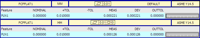
Here is an example report for a flatness tolerance:

If you select the per unit check box, flatness has two segments. The first (upper) segment is the overall flatness as described above. The lower segment is the per-unit flatness, which defines a unit's size, shape, and orientation. The per-unit tolerances control how flat every possible unit of the toleranced feature is.
You are responsible to do the following:
Select a square or rectangular unit.
Choose the size or sizes of each unit.
Control the orientation of the unit. (The Geometric Tolerance dialog box does not provide an option to do this. You need to use the Edit window.)
Controlling the Unit Orientation
You likely will use the dialog box to control most aspects of the geometric tolerance command. However, the orientation of the unit is not controlled by the dialog box. You must do that in the Edit window's Command mode. For a general overview of the syntax in Command Mode, see the Command Mode Syntax page.
In the Edit window's Command mode, with SHOWEXPANDED=YES, a flatness per unit tolerance looks like this:
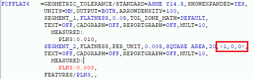
The red box highlights the orientation vector for the unit. It is always normalized and always perpendicular to the nominal surface normal of the plane. You can edit the vector. With a rectangular unit, the vector represents the direction of the first unit extent. For example, if the unit extent is 5x3 then the unit orientation vector corresponds to the 5. With a square unit, the vector represents the direction of one of the sides of the square.
Actual Value:
Conceptually, the entire toleranced feature is divided into an infinite
number of overlapping units. Each unit has the defined unit size, shape,
and orientation. Each unit has its own flatness actual value. The flatness
actual value for the entire feature is the actual value of the worst unit.
Measured Value:
There are a very large number of overlapping units containing subsets of
the measured points. For any given unit, the measured value is the minimum
distance between two parallel planes. These planes contain the unit's
subset of measured points between them. This the same as the DEFAULT
tolerance zone math type. The least squares tolerance zone math type is
not available for per-unit tolerances.
The measured value for the entire feature is the measured value of the worst unit.
The algorithm that the geometric tolerance command uses does not check every possible unit. Instead, it does an intelligent search for the worst unit. It always finds the worst unit. It can do this with much less computation time than if it checked every possible unit.
In PC-DMIS 2020.2 and later, you can control the unit orientation. The unit orientation vectors are in part coordinates. In earlier versions, with XactMeasure per-unit flatness, you could not control the unit orientation. Also, the units were aligned with the machine coordinate system rather than the part coordinate system.
In PC-DMIS 2020.2 and later, the per-unit flatness algorithm is conservative. This means the algorithm always finds the worst unit. In earlier versions, XactMeasure per-unit flatness evaluated a large number of units, but it did not always find the worst unit.
Here is an example report for a flatness per-unit tolerance. The upper label is for the overall flatness, and the lower label is for the per-unit flatness.