
In this Topic Hide
A straightness specification controls how much the feature can deviate from being perfectly straight. In other words, straightness evaluates how straight the feature is.
Straightness falls into two broad types:
An axis tolerance has a diametric zone symbol before the tolerance value:
A surface tolerance does not have the diametric zone symbol:

Straightness of an axis operates on a derived median line (or extracted median line in ISO 1101 language). This line represents the straightness form error of a cylinder's or cone's axis.
Actual Value:
This is the diameter of the smallest cylinder that contains the derived
median line.
You can use these features:
Cylindrical or conical features that have surface data. For details on the cylinders and cones that have surface data, refer to "Feature Types With and Without Surface Data".
3D constructed BF lines where the input points are the centers of circles
On cylindrical features, straightness tolerances of an axis divide up the surface data into cross sections. It then computes the center of each cross section. To maximize your chances of finding the worst cross section, we recommend that you measure the cylinder with many cross sections.
Measured Value:
This is the diameter of a cylinder that contains all the cross-sectional
centers. A best-fitting routine determines the axis of the cylinder. If
you didn't measure the measured data in cross sections, PC-DMIS gives
you an error.
On conical features, straightness tolerances of an axis divide up the surface data into cross sections. It then computes the center of each cross section. To maximize your chances of finding the worst cross section, we recommend that you measure the cone with many cross sections.
Measured Value:
This is the diameter of a cylinder that contains all the cross-sectional
centers. A best-fitting routine determines the axis of the cylinder. If
you didn't measure the measured data in cross sections, PC-DMIS gives
you an error.
You can use only 3D constructed Best Fit (BF) lines. You cannot use Best Fit Recompensate (BFRE) lines.
On 3D BF line features, straightness tolerances of an axis assume that the input points represent the centers of circular cross sections. To maximize your chances of finding the worst cross section, we recommend that you measure many cross sections.
Measured Value:
This is the diameter of a cylinder that contains all the input points.
A best-fitting routine determines the axis of the cylinder.
When the feature is a cylinder,
straightness tolerances of an axis allow a maximum material modifier  to indicate
the specification is at the maximum material condition (MMC). Alternatively,
they allow a least material modifier
to indicate
the specification is at the maximum material condition (MMC). Alternatively,
they allow a least material modifier  to indicate
that the specification is at the least material condition (LMC). This
means that as the unrelated mating envelope size (or unrelated minimum
material envelope size for LMC) deviates from the MMC (or LMC), additional
tolerance or "bonus" tolerance is added to the tolerance in
the feature control frame, yielding a total tolerance. For more information
on this bonus tolerance, see "Evaluating
Size with the Geometric Tolerance Command".
to indicate
that the specification is at the least material condition (LMC). This
means that as the unrelated mating envelope size (or unrelated minimum
material envelope size for LMC) deviates from the MMC (or LMC), additional
tolerance or "bonus" tolerance is added to the tolerance in
the feature control frame, yielding a total tolerance. For more information
on this bonus tolerance, see "Evaluating
Size with the Geometric Tolerance Command".
This example uses inches. Suppose a cylindrical hole has an axis straightness tolerance 0.002 at MMC:

The size tolerance is 0.675 plus or minus 0.025. This means the range of acceptable sizes is 0.650 to 0.700. The maximum material condition is then 0.650. If the unrelated measured mating envelope size is 0.661, then the bonus tolerance is 0.011, and the total tolerance is 0.013.
The tolerance zone math type controls the best fitting routine:
DEFAULT - This computes a minimum-zone best fit axis (also called min-max) which finds the smallest measured value given the cross-sectional centers. It is mathematically very similar to the specification, because if the points were measured densely and with high accuracy, the measured value will closely approximate the actual value.
LSQ - This does a least-squares best fit axis. It minimizes the sum of the squares of the deviations to the best fit axis. This option produces a larger measured value (it is more conservative than the DEFAULT option). But in general, this option computes more quickly.
Here is an example report for a straightness of an axis tolerance:

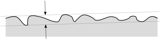
Straightness of a surface operates on line elements on a surface.
Actual Value:
This is the minimum distance between two parallel lines, containing the
entire actual line element between them. The two parallel lines lie in
an implicit workplane defined by the view of the drawing. The actual value
for an entire surface is the worst actual value of all possible line elements
on the surface.
You must use line features that have surface data. For details on the lines that have surface data, refer to "Feature Types With and Without Surface Data". To maximize your chances of finding the worst actual cross-section, we recommend that you measure the surface with many lines.
Measured Vale:
This is the minimum distance between two parallel lines. The lines contain
the surface data between them. A best-fitting routine finds the orientation
of the lines. The two parallel lines lie in a temporary (internal) workplane.
The temporary workplane’s surface normal is perpendicular to the line
feature’s line vector and to the line feature’s surface normal.
Depending on the measurement uncertainty, how many points you measured, how many cross sections you measured, and where you took the points, the measured value can be larger or smaller than the actual value. Here's an illustrated case where too few points were measured, so the measured value is smaller than the actual value:

None. Straightness of a surface doesn't allow modifiers.
The tolerance zone math type controls the best fitting routine:
DEFAULT - This computes a minimum-zone best fit line (also called min-max). It finds the smallest measured value given the surface data. It is mathematically very similar to the specification, because if the points and cross sections were measured densely and with high accuracy, the measured value will closely approximate the actual value.
LSQ - This computes a least-squares best fit line. It minimizes the sum of the squares of the deviations to the best fit line. This option produces a larger measured value (it is more conservative than the DEFAULT option). But in general, this option computes more quickly.
Here is an example report for a straightness of a surface tolerance:

If you select the per unit check box, straightness has two segments: The first (upper) segment is the overall straightness as described above. The lower segment is the per-unit straightness, which defines a unit length. The per-unit tolerances control how straight every possible unit of the toleranced feature is.
Conceptually, the entire toleranced feature is divided into an infinite number of overlapping unit lengths:
For an axis, the cylinder cross-sectional centers are divided into overlapping unit lengths.
For a surface, the surface cross section is divided up into overlapping unit lengths.
Actual Value:
Each of the infinite units has its own actual value, as defined above.
The entire feature's actual value is the actual value of the worst unit.
Measured Value:
There are a large number of overlapping units that contain subsets of the
measured points. For any given unit, the measured value is defined the
same way as overall straightness, except limited to the subset of the
measured points. The measured value for the entire feature is the measured
value of the worst unit.
Here is an example of an axis straightness per-unit tolerance. The upper segment is the overall straightness, and the lower segment is the per-unit straightness.

Here is an example of a surface straightness per-unit tolerance. The upper segment is the overall straightness, and the lower segment is the per-unit straightness.

Here is an example report for a straightness per-unit tolerance. The upper label is for the overall straightness, and the lower label is for the per-unit straightness.
