
Label Layout Wizard
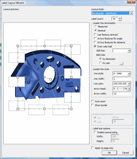
The Label Layout Wizard is a tool that lets you quickly arrange multiple labels around your CAD drawing in the Report Template Editor and determine how the leader lines are drawn. In the Report Template Editor, this wizard appears automatically whenever you insert a CadReportObject. It also appears when you select the (Settings Dialog) property for a CadReportObject.
You can also utilize this wizard in the Report window. To access it, right-click on the CadReportObject in the Report window and select Edit Object. In the Report window, the wizard displays the real part model used with your measurement routine. In the Report Template Editor, however, it displays the Hexagon test block as a filler model.
Any changes you make inside this wizard will automatically change the appearance of the CadReportObject.
This wizard contains these two main parts:
Layout Preview area
Settings area
Layout Preview area

The Layout Preview area lets you preview how the layouts will appear around the CadReportObject.
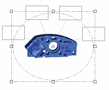
Depending on how you want your labels to appear, you can rotate labels along either a rectangular or an elliptical path by clicking on the square, white handle, located at the center of the rectangle or ellipse and dragging it to a new location. You can click and drag any of the outer white handles to size this rotation path.
If you want to relocate your part drawing, click on it and drag it to a new location.
The following options are available:
Layout
Style list
The drop-down list lets you control the spacing and rotate paths for the
labels in the Layout Preview area. You can choose
between these options:
Rectangular
- Distributed - This creates a rectangular path that labels rotate
around. The labels are distributed equally around the rectangle.

Rectangular
- Packed - This creates a rectangular path that labels rotate around.
The labels are close together along one side of the rectangle.

Elliptical
- Distributed - This creates an elliptical path that labels rotate
around. The labels are distributed equally around the ellipse.

Elliptical
- Packed - This creates an elliptical path that labels rotate around.
The labels are close together along the ellipse.

Feature
Based - This setting automatically places in the Report window
all the feature labels around the part model in locations close to each
feature's location. This is useful when you have, for example, a large
amount of edge points and you want to display all their labels in one
CAD drawing. Selecting this option disables the Label Count box and enables
the Feature Based Option area where you can define the minimum leader
line length. 
Feature Based - Restricted - This acts the same as Feature Based except that it enables the Label Count box, allowing you to restrict the number of labels that will appear in the object in the Report window. If the object needs to display more labels than you have defined, the extra labels will appear in additional instances of the CAD drawing on new pages.
Leader
Line Termination area
This area lets you choose where the leader lines from the labels will terminate
on the CAD drawing.
Measured
- This option terminates the leader line at the measured value's position.
Nominal
- This option terminates the leader line at the nominal value's position.
Use Feature
Centroid - This check box terminates the leader lines to the centroid
of the feature. 
At two
features for angle - This check box draws a single leader line
from the label that then splits into two lines pointing to the two features
making up an Angle
dimension. 
At two
features for distance - This check box draws a single line from
the label that then splits into two lines pointing to the two features
making up a Distance
dimension. 
Draw
Color Ball - This check box draws a colored ball where the leader
line terminates. The color of the ball matches the tolerance color band
for that feature's value. 
Ball Size - This list determines the size of the colored ball drawn where the leader line terminates. It becomes enabled for selection when the Draw Color Ball check box is selected. You can choose between small, medium, and large. In addition, to define a more specific size, you can type a number in this box. This reflects the diameter of the color ball in pixels.
Ball Color by Dimension - This option colors leader line termination balls with the dimension's deviation color for the worst reported axis.
Ball Color by User - This option colors leader line termination balls with a single color that you select. To set the color, click on the ... button and specify the color using the Color dialog box.
Leader
Line Style area
This area lets you define what leader lines look like in the report.
Line Style - Defines the line style:
Line styles only work at the default line width of 1. Wider lines will only use the Solid line style.
Line Width - Sets the line width in pixels.
Line Color - Defines the color of the line by setting RGB (Red, Green, Blue) values, consisting by three numbers separated by periods. You can either type in specific values for the colors, or you can select the ... item from the list to access a standard Color dialog box and select your line color from that.
Arrow Head - Defines whether or not the leader lines have Arrow Heads.
None - Lines do not have arrow heads.
Both - Lines have an arrow head at each end.
Arrow Width - Defines the width of the arrow head in pixels
Show
Border check box
This check box draws or removes a border around the entire CADReportObject
inside the template editor or Report window.
Auto
Zoom check box
This check box will automatically zoom in on the CAD display in the Report
window in such a way that it focuses the attention on only that portion
of the CAD model for which label objects are currently displayed.
Feature
Based Option area
This area becomes enabled when you select Feature Based
or Feature Based-Restricted. It contains two
option buttons, mm and inch,
and an Offset box. You can use the Offset
box to define the minimum leader line length used with the labels. Depending
on available room in the CadReportObject,
the leader line length may grow, but it will never go below this minimum
value.
Label
Count box
This changes the maximum number of labels a report's page will display.
It becomes disabled when you select Feature Based.
Label
Size Options area
This area lets you switch between automatic or manual sizing of label objects.
To make your label objects a specific size, click on Enable
Manual Sizing and type in values in the Width
and Height boxes.
Changing the labels sizes affects design purposes only. It does not affect label sizes in the actual Report window.
This area only appears when using the wizard in the Report Template Editor.
Apply
to page only check box
Applies the changes made in the wizard to just the current page.