Click the Advanced >> button in the Scan dialog box to display the full dialog box if necessary.
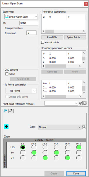
Scan dialog box for Linear Open Scan
Click the Graphics tab to display the CAD controls area. You can use this area to specify the CAD surface elements that define the "Theoretical Points".

CAD controls area
In some cases, a scan might start over a certain surface and travel over many other surfaces before completion. In such cases, PC-DMIS does not know which CAD elements to use to generate the scan. It must therefore search through every surface in the CAD model. If the CAD model has many surfaces, it might take a long time before the scan generation is successful.
To use this functionality to select CAD surfaces,
you must have the ability to import and use CAD surface data. Ensure that
you select the Draw Surfaces button ( ). If you don't, when you
click on the CAD model, the nearest wire gets selected instead of the
selected surface.
). If you don't, when you
click on the CAD model, the nearest wire gets selected instead of the
selected surface.
To avoid this delay:
Select the Select check box.
Click on the appropriate surfaces. Once a CAD surface is selected, it is highlighted in the Graphic Display window. The status bar displays the number of surfaces that you selected.
If you mistakenly select a surface, press Ctrl, and click on that surface a second time. This deselects the surface. Clicking the Deselect All button deselects all highlighted surfaces at once.
Once you are done selecting surfaces, clear the Select check box. The selected surfaces are kept.
If you clear the Select check box, PC-DMIS assumes any clicks on the surface to be those that create the scan path.
The following options are available:
Select check box - Enables you to select the CAD surface and wireframe elements used to find the nominal.
Deselect All button - Deselects all of the highlighted surfaces at once that were created with the Select check box.