
The LeaderLine object lets you draw leader line (a connecting line) between a Label object and a CadReportObject. To do this, simply select the object, then click and drag it from one object to the other.
If done properly, the leader line automatically snaps between the two objects so that if you later change their locations, the leader line changes size and moves accordingly. For example, this figure shows a CadReportObject object with three Label objects around it all with connecting LeaderLine objects.

Three Label objects with LeaderLine objects drawn to a CadReportObject
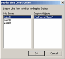
If the leader line can't detect the two objects, a Leader Line Construction dialog box appears, allowing you to select the two objects for the leader line.

Leader Line Construction dialog box
If you delete the Label or a CadReportObject object, PC-DMIS also deletes the leader line object automatically.
In the actual Report window, depending on the location of the label to the feature, the leader line attaches to either one of the edges or corners of the label. Consider this graphical example. It illustrates that where you position the labels (rectangles) in relationship to the feature (red circle) changes where the leader line connects (green dot) on the label.

Graphical Example of Labels and Leader Line Connection Positions
The following properties are available:
LeaderLineVisibility
This sets the visibility state of the selected leader line. TRUE shows
the leader line. FALSE hides it.
Object1
Defines the first of the two objects between which the leader line will
be drawn.
Object2
Defines the second of the two objects between which the leader line will
be drawn.