Probe Toolbox - CWS Parameter tab
The CWS Parameter tab in the Probe Toolbox (View | Other Windows | Probe Toolbox) is available once the system has been appropriately configured:
You must configure the CWS as the active laser system. Usually, the factory does this locally during the startup procedure or by a service engineer.
With the system configured, you must next define a probe with the correct properties. You can construct the probe in the Probe Utilities dialog box. You should use the OPTIV_FIXED selection and a lens that includes CWS. You should define this in the USRPROBE.DAT file if not provided by the factory.
The CWS Parameter tab can include the following information:
Frequency (Measurement Rate)
The measurement rate sets the number of measured values that the optical sensor records per unit of time. For example, when the measurement rate is set at 2000 Hz, 2000 measurement values are taken per second. The intensity indicator on the display can help you select the correct setting.
Setting Range
As a rule, you should strive to measure at the highest possible measurement rate in order to acquire as many measurement values in as little time as possible. In the case of surfaces with very low reflectivity, it may be necessary to reduce the measurement rate. This has the effect of illuminating the optical sensor‘s CCD-line longer and thus makes it possible to perform measurements, even if the reflected intensity is very low.
Overmodulation of the CCD-line on highly reflective surfaces and at small measurement rates can lead to measurement errors. If the intensity indicator on the CWS controller box displays a blinking ,,Int: 999", or the Probe Readouts window displays an intensity value in red at or near 100%, overmodulation is occurring.
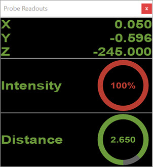
Probe Readouts window showing overmodulation
When overmodulation occurs, select the next-highest measurement rate. If the maximum measurement rate (2000 Hz on CHRocodileS, 1000 Hz on CHR150E) is already set, you can reduce the reflected intensity in one of two ways:
Position the sensing head in the upper or lower threshold of the measurement range.
Engage the autoadaptfunction (where the Auto Intensity parameter is set to ON). This adapts the lamp intensity continuously, depending on the part reflection. Here, a dark reference is not used. This is the method supported in PC-DMIS.
Exposure time (Brightness Value)
You can select the exposure time (brightness value) here if the AUTO Intensity parameter is set to ON.
The brightness of the lamp is modulated such that you achieve a defined percentage of the modulation amplitude. The value can lie in the range of 0% to 75%. For most applications, a recommended brightness value is between 20% and 40%.
Auto Intensity
This value defines the relative pulse duration of the LED, and with it the effective brightness of the light source.
If you are measuring a highly-reflective surface on which the highest measurement rate still results in overmodulation, then it makes sense to reduce the exposure time.
The best way to measure a poorly-reflective surface with a high measurement rate is to use a longer pulse duration.
Auto Intensity: OFF
Turn the Auto
Intensity button ( )
off to use the current light intensity of the LED.
)
off to use the current light intensity of the LED.
Auto Intensity: ON
With the Auto Intensity button set to ON, the independent adjustment of flash time for the LED during an exposure time allows for you to automatically receive the best intensity settings when measuring on variable surfaces. This also allows for an optimal signal-to-noise ratio.
The system modulates the brightness of the lamp to achieve a defined percentage of the modulation amplitude. The value can lie in the range of 0% to 75%. For most applications, the recommended brightness value is between 20% and 40%.
Offset
This is the offset distance that the machine moves to in the measurement direction in addition to the measurement position.
Intensity filter
This value defines the threshold between noise and the measurement signal. The software recognizes that the peaks that fall beneath this threshold are invalid, and show on the display as the measurement value "0".
For a valid measurement, the intensity should fall between 0 and 999 on CHRocodileS or 99 on CHR150E; otherwise, you must change the measurement rate.
If you measure the distance to a surface with low reflectivity, the intensity of the reflected light can be too low, and you must reduce the measurement rate. For a measurement rate under 1 kHz, the threshold value should be 40 on CHRocodileS or 25 on CHR150E. This prevents measurement values of too low an intensity, which rise only slightly above the noise, and would falsify the measurement.
With a measurement rate of 1 kHz and higher (only for CHRocodileS), a threshold of 15 is best to fully exploit the device’s dynamics.
Focus
This section has four boxes for the X, Y, Z, and Signal
Quality. Click the Auto Focus button  on the right to execute
a focus or surface measurement to display the X, Y, Z, and Signal Quality
values.
on the right to execute
a focus or surface measurement to display the X, Y, Z, and Signal Quality
values.
For more details, see "CWS Parameters" in the PC-DMIS Vision documentation.