Creating a Mesh/CAD Alignment
To create a Mesh to CAD alignment, do the following:
Ensure that you have an imported CAD model
in the Graphic Display window and a MESH
command in the measurement routine. These elements are required to
align a mesh to the CAD.
Select the Insert | Mesh
| Alignment menu option or select the Mesh
Alignment button ( )
on the Mesh toolbar. You can also access
this dialog box by typing the MESHCADBF
command in the Edit window’s Command mode between the ALIGNMENT/START
and the ALIGNMENT/END commands.
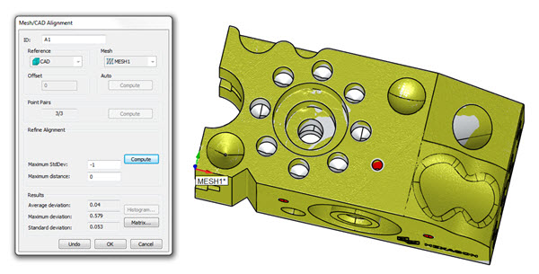
The Mesh/CAD alignment dialog box appears:
)
on the Mesh toolbar. You can also access
this dialog box by typing the MESHCADBF
command in the Edit window’s Command mode between the ALIGNMENT/START
and the ALIGNMENT/END commands.
The Mesh/CAD alignment dialog box appears:
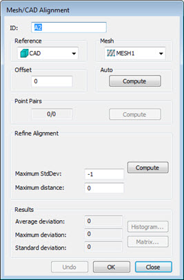
Mesh/CAD Alignment dialog
box
For a complete description of
the Mesh/CAD Alignment dialog box, see the topic
"Mesh/CAD
Alignment Dialog Box Description" in the PC-DMIS Laser documentation.
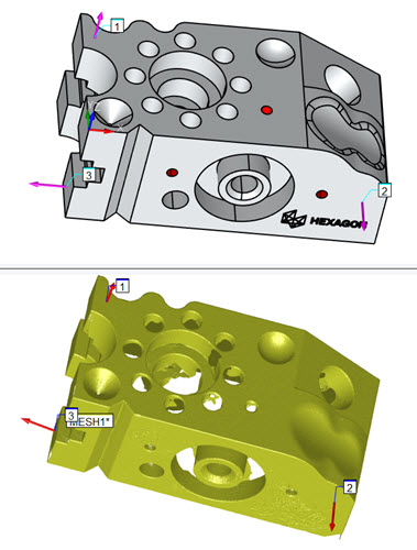
A temporary and split-screen view of the CAD
model and the mesh appears in the Graphic Display window. You can
use this split-screen view to visually see the alignment taking place.
Select your point of reference from the Reference
drop down list; usually, either the CAD model itself or a defined
Mesh is available. The Mesh is aligned to the selected reference.
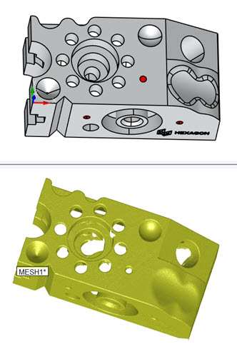
Split-screen view showing
the CAD model on the top view, and the mesh on the bottom view
If you have more than one mesh in your measurement
routine, choose the mesh from the Mesh list.
Perform the alignment:
Click the Compute button in the Auto
section. You should only use this when you have a full scan of the
external faces of the part. This automatically performs an alignment
of the Mesh to the CAD and also a refinement on the alignment as it's
generating.
If the auto compute
does not compute a good alignment, use the Point
Pairs area to perform a rough alignment. This brings the mesh
close enough to the CAD if it's not already close. You can then refine
the alignment further if needed. You should use this type of alignment
if the mesh is not complete or it contains scanned data belonging
to a fixture, table, or other similar feature.
Click a desired
number of points on the mesh.
Click corresponding
locations on the CAD model. 


The more points
you take around the different areas of the model and mesh, the better
the rough alignment.
Click Compute
to create the rough alignment.
Next, use the Refine Alignment area whenever you want to refine
your alignment, thereby bringing the mesh closer to your CAD model.
In order to be able to obtain a good refined alignment, the mesh points
should be close enough to the CAD points through an initial rough
alignment.
Define the total
number of random sample points to use in each iteration in the Total Points.
Define the number
of iterations in the Maximum Iterations
box.
Define the maximum
standard deviation for the auto alignment execution between the points
in the mesh and the CAD model using the Maximum
StdDev box. When the auto alignment command is executed, if
the standard deviation of the Mesh/CAD deviations is greater than
the maximum value defined, you can select point pairs to get a better
alignment. The default value of -1 is equivalent to an infinite allowed
standard deviation.
Define the maximum
distance of the points from the CAD in order for use in the best fit
routines. The default value is 0. In this case, an internal max distance
based on the size of the mesh is used.
Click Compute
to refine the alignment.
If a portion of the mesh doesn't align nicely
with the CAD, you can click the Undo button
and recompute the alignment using the same type of alignment with
additional parameters, or you can try a different alignment.
If you have a surface model representing a
sheet metal part, and you want to align to the offset faces, define
an Offset value representing the constant
thickness of the sheet metal part.
Use the Results area
to see how well the mesh aligned with the CAD. Make any changes to
the Offset or Refine
Alignment values to improve the alignment if necessary. If
any changes are made, be sure to click the Compute
button to regenerate the alignment with the new values.
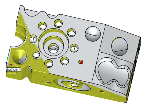
Once you're satisfied with the alignment, click
Create. PC-DMIS closes the temporary split-screen
view and places the MESHCADBF command
in the Edit window. See the "MESHCADBF
Command Mode Text" topic.
Example of a completed Mesh
to CAD alignment