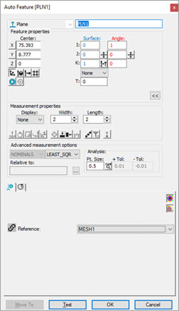
You can extract a Laser Auto Feature from a mesh data object with the Laser Auto Feature dialog box.
Please see "Extracting a Laser Auto Surface Point from a Mesh" for details about extracting Laser Auto Surface Points from a Mesh data object.
If there's only one Mesh in your measurement routine, PC-DMIS defaults to the Mesh as your reference data object. If there's a COP (or more than one COP) and one or more Mesh data objects, you need to select the correct reference data object from the Reference list of the Feature Extraction tab in the Probe Toolbox.
When extracting the Laser Auto Feature from a Mesh
data object, all the triangle vertices inside the extraction zone, defined
by the horizontal and vertical clipping, are first considered. To view
the points which fall within the extraction zone, click the Show/Hide
segregated points button ( ) on the Laser Scan Properties tab.
Click the Test button to measure the feature and view its measured points.
Examples of features extracted from a Mesh data object
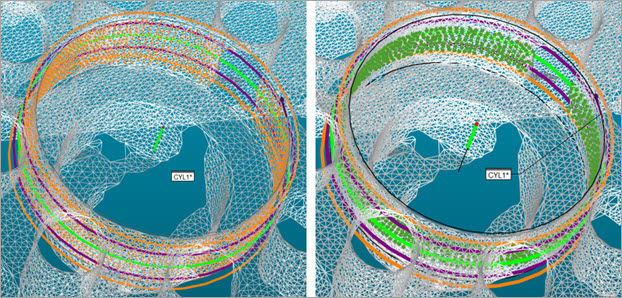
Example of a Cylinder Auto Feature extracted from a Mesh data object
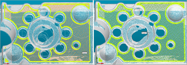
Example of a Plane Auto Feature extracted from a Mesh data object
Orange points show segregated points found within the extraction zone.
Green points show measured points after PC-DMIS performs the test operation when you click the Test button.
More:
Extracting a Laser Auto Surface Point from a Mesh