Feature Extraction - Ring Band
You can use the Ring Band area to calculate the feature’s projection plane and normal vector. The feature data is projected up into the ring band's plane. The following Ring Band controls are used to accomplish feature extraction for circles, round slots, and square slots:
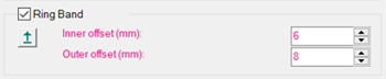
Ring Band - When you select this option, the software enables these Ring Band options:
Plane Selection

Prior to PC-DMIS version 2020 R1, when you select a cylinder on the CAD
model with the Ring Band option, the software
sets the Ring Band on a plane. The plane is a virtual plane located in
the lower end of the cylinder feature based on the design of the CAD model.
The problem is that the plane is not real, and it is not correct to define a cylinder by piercing a virtual plane to get its intersection point. The reason is that, depending on the part you are inspecting, there may be multiple components between the cylinder and the plane.
As a result, the nominal value of the intersection point between the cylinder and the plane is off in the Z axis by some value. You could get a correct measured value if you set the Vertical Clipping so that the real plane gets included in the Ring Band area, and therefore measured at the correct Z location. The problem is with the reported deviation since the nominal value is wrong.
When you select the Ring Band check box, you enable the Plane Selection On/Off button. You can find this button in the Ring Band section of the Feature Extraction tab of the Probe Toolbox for Laser. Click the button and select the desired plane in the CAD model to set the ring band controls on that plane, and to have the software properly update the nominals.
When you program a 2D feature (Circle, Polygon, Round Slot and Square Slot), you can select the plane that PC-DMIS programs and extracts the feature from. To do this, click the Plane Selection On/Off button and, in the Graphic Display window, select the plane. The Z nominal for the 2D feature will move to that plane. PC-DMIS calculates the selected plane at the defined Depth location from the selected plane. The feature is then projected on this plane.
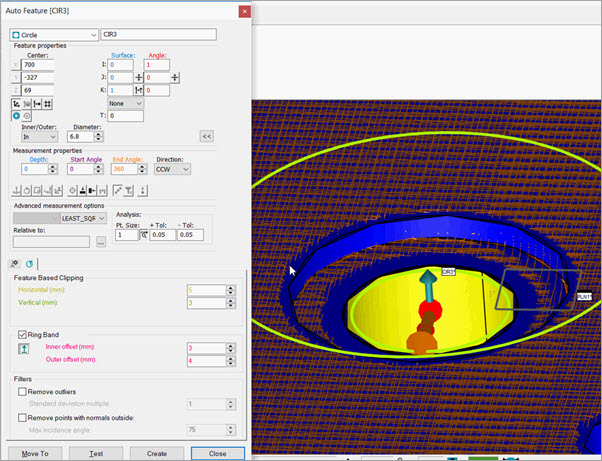
Example prior to selecting the Ring Band plane to extract 2D feature: Z nominal = 69

Example after selecting the Ring Band plane to extract 2D feature: Z nominal = 70
It's very important to notice that the Depth parameter setting is crucial for the calculation. The reason is that the feature extractor uses this value to search for the points to calculate the 2D feature. The calculation uses the Depth parameter value relative to the selected plane.
Because of this, it is your responsibility to ensure that there are points at that depth in the pointcloud where you want to extract the feature.
Inner offset and Outer offset
PC-DMIS uses these default values when Auto Circle, Auto Round Slot, and Auto Square Slot are disabled:
Inner offset = 0.4x the theoretical diameter value
Outer offset = Inner offset value + 3 mm
Inner Offset - This value provides the offset from the theoretical feature radius or form for the inner edge of the ring band. This value is expressed in measurement routine units and must be greater than or equal to zero (a value of zero means an inner edge of the ring band coincides with the feature nominal.) See the image below.
Outer Offset - This value provides the offset from the theoretical feature radius or form for the outer edge of the ring band. This value is expressed in measurement routine units and must be greater than the Inner Offset value. See the image below.
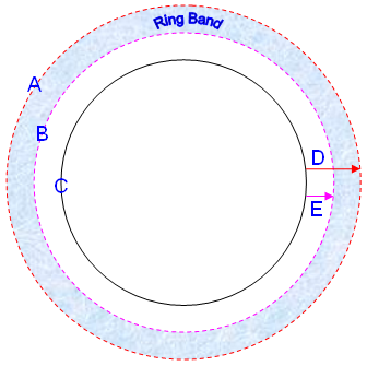
(A) Ring band Outer Edge
(B) Ring Band Inner Edge
(C) Feature Theoretical value
(D) Outer Offset
(E) Inner Offset