Basic lathes have no viable C-Axis and cannot measure past the spindle center (X > 0). You can define basic lathes in the NC Server application.
For information on the NC Server operation, please consult the NC Server PDF manual provided with your NC Server application. You can download NC Server from the Universal Updater application.
Do not select rotary tables in PC-DMIS with basic lathes.
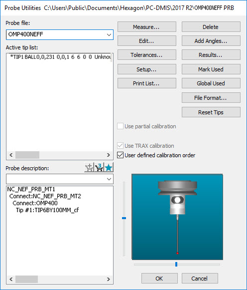
The Off-Center Sphere Calibration method records at least three hits (either side and on top) in the XZ plane.
Build the probe tip in the Probe Utilities dialog box as shown below:
Probe Utilities Dialog Box for Off-Center Sphere Calibration
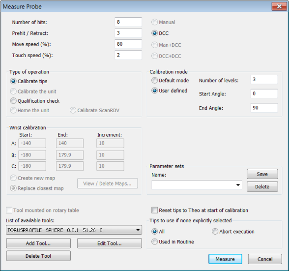
Select the calibration measurement routine and number of hits from the Measure Probe dialog box, as shown below:
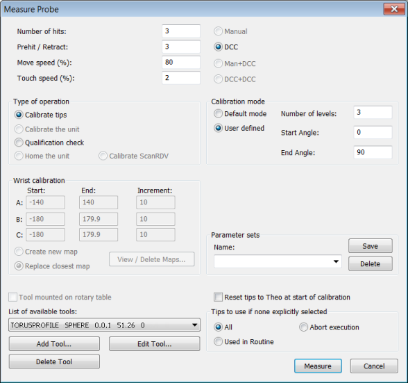
Measure Probe Dialog Box for Off-Center Sphere Calibration
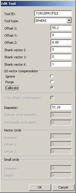
To enter the details of the sphere calibration in the Edit Tool dialog box, click Edit Tool.
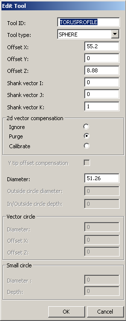
Edit Tool Dialog Box for Off-Center Sphere Calibration
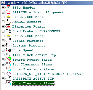
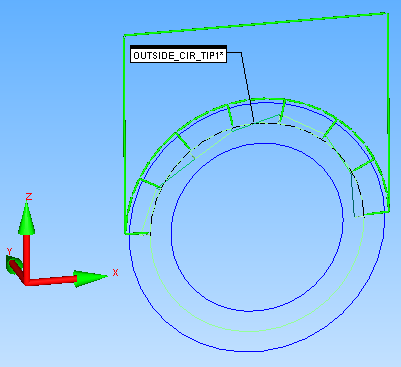
The calibration measurement routine that is created uses a PC-DMIS Auto Circle feature (OUTSIDE_CIR_TIP1) as described below:
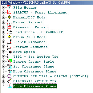
Calibration Measurement Routine for Off-Center Sphere Calibration
PC-DMIS displays the measurement routine graphically as follows:

Off-Center Sphere Calibration Measurement Routine Graphical View
The journal file for a calibration on a section of the Torus profile is shown below.
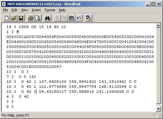
Off-Center Sphere Calibration Journal Output
The journal file is used to compute and update the Probe Tip Radius, Probe Length, and Probe Tip X Offset.
To open the Edit Probe Data dialog box, click Edit in the Probe Utilities dialog box:

Edit Probe Dialog Box
Offsets in the Y axis are zeroed as it is impossible to compute Y offset information with this form of calibration. The sphere and probe tip must be mounted accurately in the XZ plane. No spindle rotation is needed.
The 2D Vector Calibration measures the profile of a semi-circle in the XZ plane and generates a look-up table to compensate for lobing effect. The selection of eight or more hits and selection of 2D Vector Calibration in the Edit Tool dialog box invokes the Vector Calibration.
Edit Tool for 2D Vector Calibration
The Measure Probe dialog box is shown below for reference:
Measure Probe Dialog Box for 2D Vector Calibration
The Sphere Calibration for the 2D Vector Calibration measurement routine appears unchanged from the Off-Center Sphere Calibration method.
Measurement Routine for 2D Vector Calibration
The Graphical View shows the eight hit points as programmed:
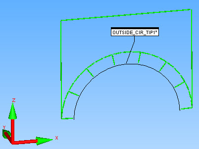
2D Vector Calibration Measurement Routine Graphical View
The journal file is shown below:
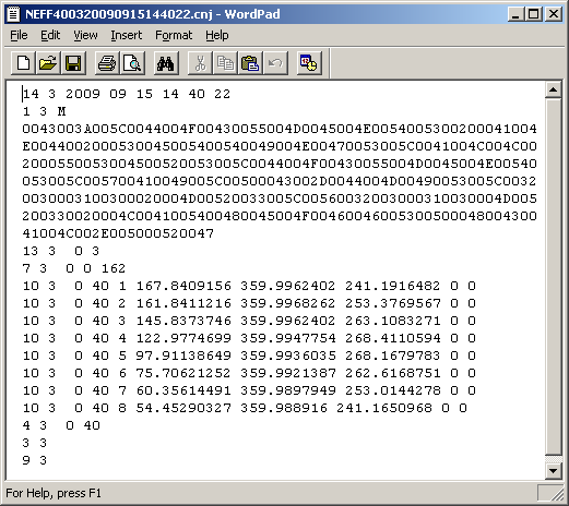
2D Vector Calibration Journal File
The Report is shown below:
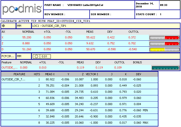
2D Vector Calibration Report
Graphically, the Out of Roundness is drawn in the Graphic Display window as shown below:

2D Vector Calibration Out Of Roundness Graphical View
Running the same journal file after the completion of the Vector Calibration shows an improvement to Circularity due to the 2D Vector Compensation.
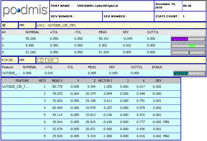
Report after 2D Vector Calibration
The Graphical View is then drawn as shown below:
Graphical View after 2D Vector Calibration