Extended lathes can measure past the spindle centre (for example, X < 0). Hembrug lathes are examples of such machines. Calibration of offsets for these machines can be simplified with a single outside circle feature centred at the origin, rather than the inside and outside circle as done previously. A simpler option is to use a spindle-mounted sphere, and use it to incorporate a 2d Vector Compensation if required.
The calibration scheme that you choose must manage the transition between taking hits at different sides of the spindle center to avoid collisions. To do this, the circle feature centered at the spindle center is broken up into two semi-circles, and a Move ClearPlane command is interposed between the two. This scheme is only adopted to simplify calibration, and measurement routines will continue to measure only with X > 0.
Extended lathes are set up by indicating a non-zero minus limit for the X axis and a rotary table axis in NC Server application. For information on how to define an extended lathe, see the NC Server documentation.
For information on the NC Server operation, please consult the NC Server PDF manual provided with your NC Server application. You can download NC Server from the Universal Updater application.
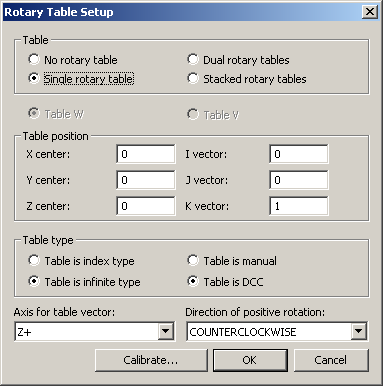
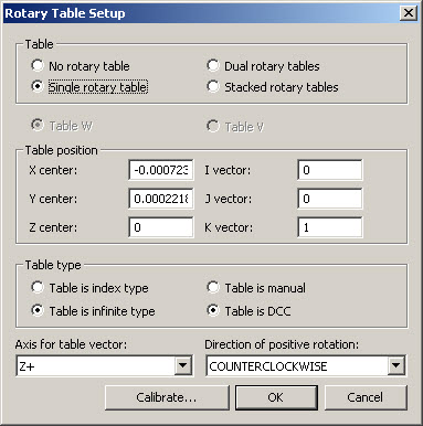
Select Edit | Preferences | Rotary Table Setup, ensure the Single rotary table is selected, and clear the offsets if you are calibrating from scratch as shown below:
Rotary Table Setup Dialog Box
To construct the probe as normal, navigate to the Insert | Hardware Definition | Probe option from the main toolbar.
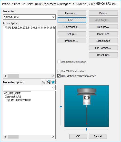
Probe Utilities Dialog Box for Extended Lathes
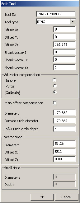
Once you define the probe, click Edit, and add a new Ring Tool. Enter the ring diameter in the Diameter and Outside Circle Diameter boxes since this will be used to create the circle features - one on the right-hand side (X>0) of the spindle and the other on the left-hand side (X<0).
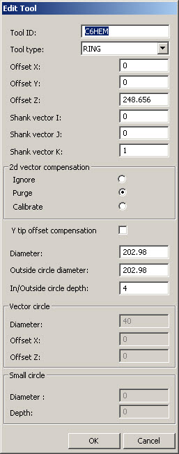
Edit Tool Dialog Box for Ring Calibration
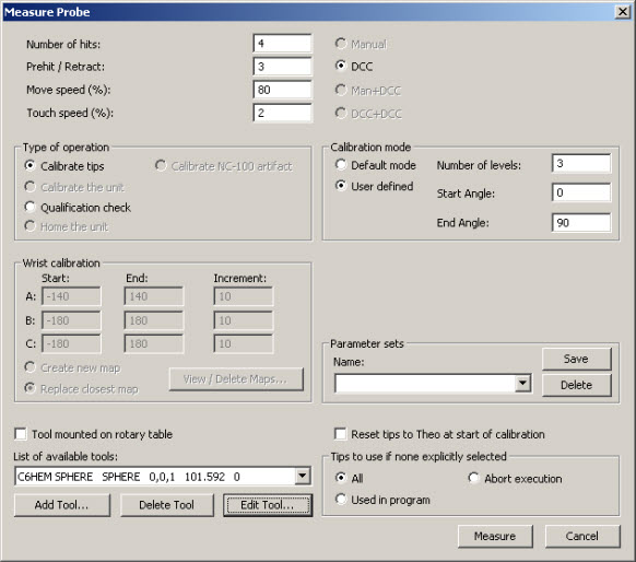
The 2d Vector Compensation is shown to be turned off and the Y Tip Compensation omitted although these options are still available if required. Click OK, and then create the calibration measurement routine. To do this, click Measure from the Probe Utilities dialog box to display the Measure Probe screen.
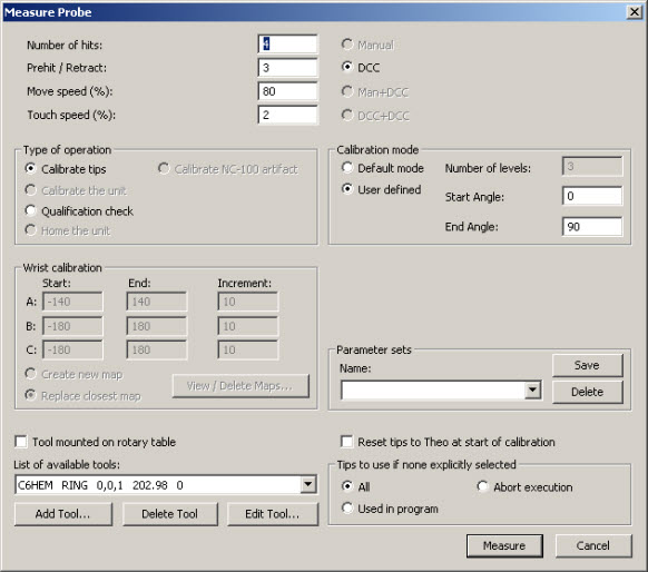
Measure Probe Dialog Box for Extended Lathe
Click Measure to create the calibration measurement routine shown below:
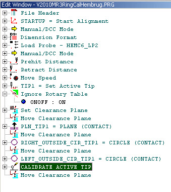
Calibration Measurement Routine for Extended Lathe
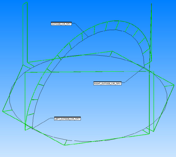
A single outside circle and a plane are needed on the artifact used for calibration. The measurement routine generated splits the circle into two semi-circles.
The right-hand circle will be measured by rotating the artifact. Hits are taken along the X axis at X>0.
The left-hand circle will be measured by rotating the artifact. Hits are taken along the X axis at X<0.
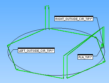
Calibration Measurement Routine Graphical View
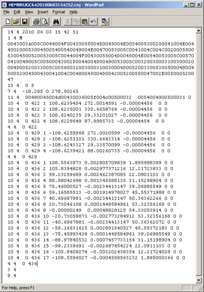
Create and run the measurement routine as normal to generate the journal file shown below:
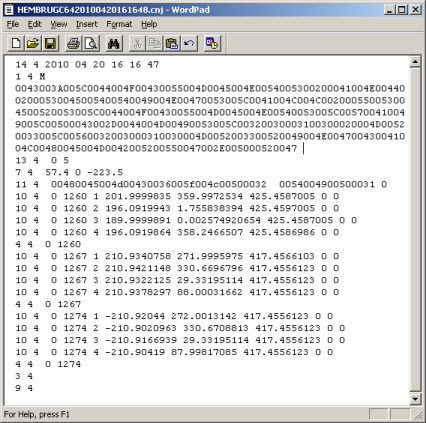
Extended Lathe Journal File
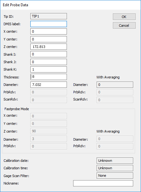
From the Probe Utilities dialog box, click on the Active Tip from the list, then click Edit to open the Edit Probe Data dialog box to view the updated values.
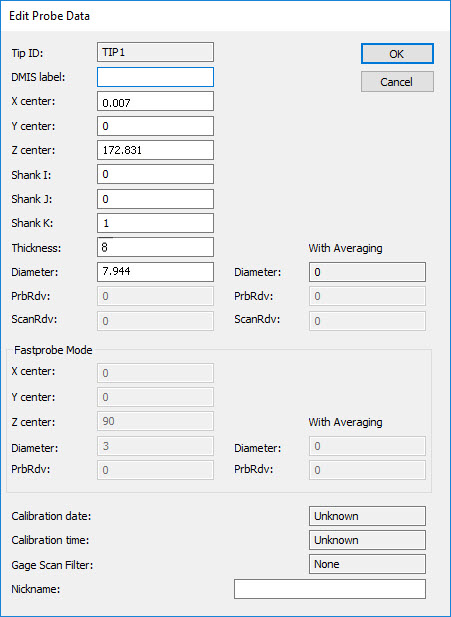
Edit Probe Data Dialog Box for Extended Lathe
Select Edit | Preferences | Rotary Table Setup to view the updated Rotary Table values.
Updated Rotary Table Setup Dialog Box for Extended Lathe
Dimensioning the calibration measurement routine is instructive as shown below:
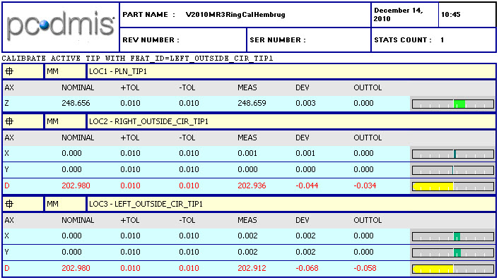
Extended Lathe Dimensioned Calibration Measurement Routine
To perform the post-calibration sanity check, switch off the Ignore Rotary Table in the measurement routine, clear the Calibrate Active Tip line, and re-run the journal file (or better still, run the measurement routine on the machine) to see if a near-perfect result is achieved.
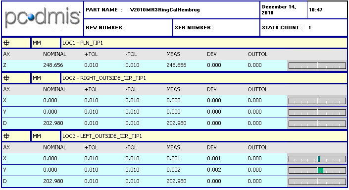
Extended Lathe Updated Report
Ring Calibration with 2d Vector Compensation
To add 2d Vector and Y Tip Offset Compensation, by enable it in the Edit Tool dialog box. To open the Edit Tool dialog box, click Edit from the Probe Utilities dialog box.
Edit Tool Dialog Box for Ring Calibration with 2d Vector Compensation
Create the calibration measurement routine as before. In this case, the 2d Vector Calibration circle has been edited to measure eight hits instead of five to match to saved journal file data.
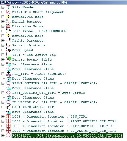
Measurement Routine for Ring Calibration with 2d Vector Compensation
Run the measurement routine to display the following in the Graphic Display window:

Measurement Routine for Ring Calibration with 2d Vector Compensation
This measurement routine generates a journal file as shown below. In this case, the journal file has been created from parts of a journal file from outside circle measurements on a Siemens NEF400 machine using the non-extended lathe groove calibration.
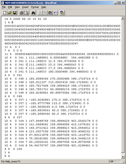
Journal File for Ring Calibration with 2d Vector Compensation
Starting again from nominals for the tip and rotary table and using the dimensioning shown above, PC-DMIS produces the following report:
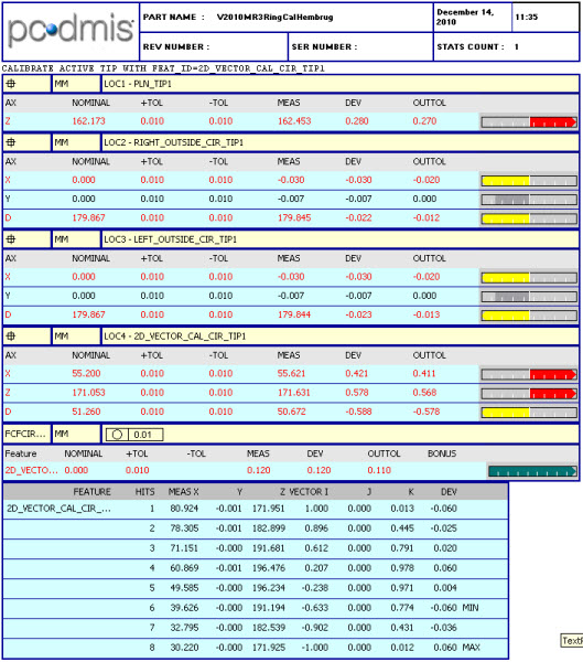
Updated Calibration Report for Ring Calibration with 2d Vector Compensation
Graphically, the Out of Circularity found during calibration is shown below:

Updated Graphical View of Ring Calibration with 2d Vector Compensation
The post-calibration sanity check is done as before, which generates the following report:
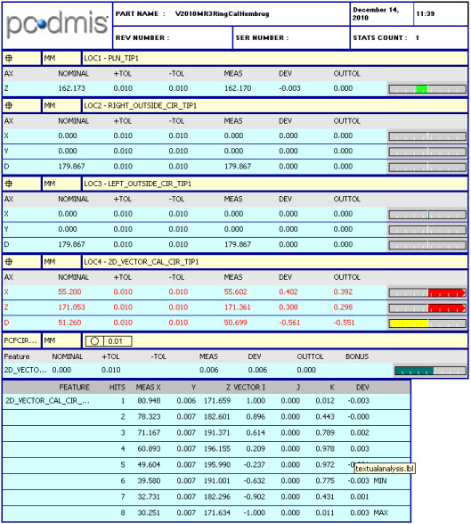
Ring Calibration with 2d Vector Compensation Post-Calibration Report
Graphically, the results for Circularity are near perfect as shown below:

Ring Calibration with 2d Vector Compensation Post-Calibration Graphical View
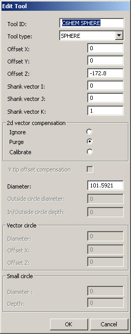
Add a Sphere Tool from the Probe Utilities dialog box by clicking Edit. Click OK when done.

Edit Tool for Adding a Sphere Tool
From the Probe Utilities dialog box, click Measure to display the Measure Probe dialog box.
Measure Probes Dialog Box for Sphere Calibration
Make the necessary change, and then click Measure to create the Calibration measurement routine as shown below:

Sphere Calibration Measurement Routine
The Graphical View of this measurement routine is shown below. Note that the number of hits for the outside circle has increased.
Graphical View of Sphere Calibration Measurement Routine
Create and run the measurement routine as normal. A journal file is created, similar to the following:
Sphere Calibration Journal File
From the Probe Utilities dialog box, click on the active tip from the list, then click Edit to open the Edit Probe Data dialog box shown below to view the updated values.
Sphere Calibration Edit Probe Data Dialog Box
Select Edit | Preferences | Rotary Table Setup to view the updated Rotary Table values.

Sphere Calibration Rotary Table Setup Dialog Box
Dimensioning the calibration measurement routine is instructive as shown below:
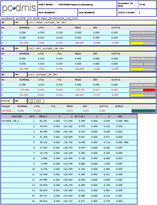
Sphere Calibration Dimensioned Calibration Measurement Routine
Turn the Ignore Rotary Table off, clear the CALIBRATE ACTIVE TIP and then re-run the journal file. The report is near perfect as shown below:
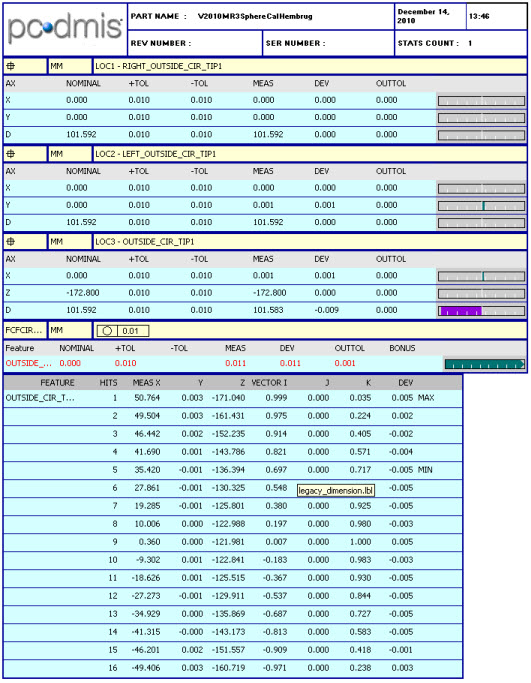
Updated Sphere Calibration Report
Sphere Calibration with 2D Vector Compensation
Add the Sphere Tool with 2d Vector Compensation as shown below. Click Edit from the Probe Utilities dialog box to open the Edit Tool dialog box.
Edit Tool Dialog Box for Sphere Calibration with 2d Vector Compensation
From the Probe Utilities dialog box, click Measure to display the Measure Probe dialog box. Make any changes and then click Measure to create the measurement routine. By default, it looks the same as a standard Sphere Calibration routine.

Initial Graphical View of Sphere Calibration Measurement Routine with 2d Vector Compensation
Re-running the new journal file after this kind of calibration emphasizes the effect of 2d Vector Compensation as shown below:

Updated Graphical View of Sphere Calibration Measurement Routine with 2d Vector Compensation
Dimensioning the calibration measurement routine is instructive as shown below:
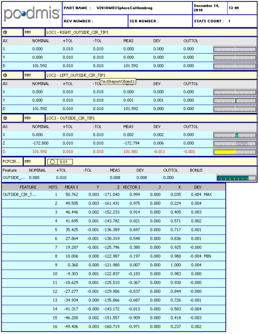
Dimensioned Measurement Routine Report for Sphere Calibration with 2d Vector Compensation