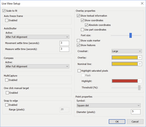
Live View Setup dialog box - Manual Mode
To open the Live View Setup dialog box, select Edit | Graphic Display window | Live View Setup from the menu, or right-click within the Vision tab and select Setup from the resulting shortcut menu.
The Live View Setup option is only available if the Vision option is enabled on your LMS license or portlock.
The Live Image Setup dialog box allows you to configure how the image appears in the Vision tab of the Graphic Display window. It contains these controls:
Scale to Fit - This check box determines whether PC-DMIS scales the display of the part to fit within the limits of the Graphic Display window. This check box is only available on some optical machines.
Auto freeze frame
When you select the Enabled check box, you can press the Live View Freeze button to toggle it on and off at measurement routine execution time. This action freezes the measured points on the screen until the next points are available for display.
This is also useful for machines where "image tear" occurs during stage movements.
AutoShutter
AutoShutter detects when a target (which may consist of multiple ROIs) is ready to measure points. The three criteria for readiness are:
The ROI is entirely within the FOV.
The stage has stopped moving.
The user-defined delays have elapsed.
When these criteria are satisfied, PC-DMIS automatically takes the points and proceeds to the next ROI.
PC-DMIS uses the options in this area when you select
AutoShutter  from
the bottom of the Vision tab (see "Live
View Controls").
from
the bottom of the Vision tab (see "Live
View Controls").
AutoShutter does not fire for DCC mode features with Manual Pre-Position enabled.
Active - This option determines when the software uses the AutoShutter capability to measure features. The options are: Always, After Partial Alignment, or After Full Alignment.
Movement settle time (seconds) - This box specifies a settle time (in seconds) before point detection takes place. This settle time begins once the current ROI that was not entirely in the FOV has entirely entered the FOV. You can use this field to slightly delay the automatic point detection to review and improve ROI placement within the FOV.
Measure settle time (seconds) - This box specifies a settle time (in seconds) before point detection for the FIRST ROI of a feature, even if this ROI is already entirely in the FOV. You can use this field to slightly delay the automatic detection to review and improve ROI placement within the FOV. This value is only applied to the first ROI of a feature.
The Movement Detected settle is the dominate value if it conflicts with the Measure Feature settle value.
Feature Compass
The Feature Compass features are only available in Manual mode.
The Feature Compass guides you to move the stage to get the next feature into the Field Of View by showing an arrow and a distance to move.
Active - Determines when the software uses the Feature Compass capability to measure features. The options are: Always, After Partial Alignment, or After Full Alignment.
PC-DMIS applies the Active
option when you select the Feature Compass  from the bottom
of the Vision tab (see "Live
View Controls").
from the bottom
of the Vision tab (see "Live
View Controls").
MultiCapture
To speed up the execution, the MultiCapture functionality causes the software to look at features ahead in the measurement routine and create groups that PC-DMIS can execute within a single camera picture (Live View). The software bundles them together and executes them simultaneously. Mark the Enabled check box to use this functionality.
PC-DMIS marks this check box by default to speed up measurement. Clear this check box when you want more visual data on each feature as it is measured.
The MultiCapture area of the dialog box is only active in DCC mode or in Manual mode when the AutoShutter conditions have been met.
 MultiCapture Rules and Limitations
For example, suppose you have five edge point features that all fit within a single Live View and you have MultiCapture enabled. Instead of the machine measuring the five edge point features separately during execution, PC-DMIS displays a MultiCapture overlay for the entire feature set. This overlay provides information about what features are in the group and how many. PC-DMIS then executes them simultaneously as if they were a single feature.
The sample MultiCapture overlay here shows five edge points combined into a single grouping. The overlay provides the following information:
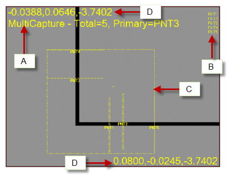
The MultiCapture message lets you know that you are in MultiCapture mode. It displays the total number of features to be measured in the current grouping, and the primary feature in that grouping.
This displays all the features within the MultiCapture region to be measured.
The dotted rectangular box is the MultiCapture region. It bounds all the features for the current grouping.
The numbers provide the XYZ coordinates for the top-left and bottom-right corners of the MultiCapture region.
One-click manual target
Select the Enabled check
box in this section to enable the Manual Targets Single
Click Execution feature. When enabled at execution time, PC-DMIS
displays a larger black and white crosshair cursor  on the Live Image View display. Instead of dragging and dropping a manual
target to a desired location on a feature, position the crosshair to the
targeted location, and click the left mouse button. If you enable Snap Mouse Click to Edge, PC-DMIS automatically
performs edge detection to snap the crosshair to the edge.
on the Live Image View display. Instead of dragging and dropping a manual
target to a desired location on a feature, position the crosshair to the
targeted location, and click the left mouse button. If you enable Snap Mouse Click to Edge, PC-DMIS automatically
performs edge detection to snap the crosshair to the edge.
Snap Mouse Click to Edge
When you mark the Enabled check box and you are programming features in the Vision tab, PC-DMIS Vision detects the nearest edge and snaps the target anchor points to that edge. The value in the Range (pixels) box indicates the distance the software searches for this edge. If you have a blurred edge that you cannot bring into focus, you may find it necessary to not use snap to edge to reliably specify anchor points when programming a feature. This also applies at execution time for Manual Targets.
The Snap Mouse Click to Edge
 found at the bottom of the Vision tab also enables
or disables this functionality (see "Live
View Controls").
found at the bottom of the Vision tab also enables
or disables this functionality (see "Live
View Controls").
Overlay properties
This area lets you set the properties for various overlay elements that can appear in the Vision tab.
Show textual information - This check box show or hides any live image informational overlays that appear inside the Vision tab.
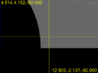
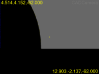
Show coordinates - This check box determines whether or not PC-DMIS displays coordinates inside the Vision tab.
Absolute coordinates - When you select this check box, the software displays the overlay coordinates as absolute values. For absolute values, the top-left and bottom-right coordinates show the actual position of those corner points in the current machine coordinates. If you do not select this option, the software displays relative values. For relative values, the top-left corner is shown as 0,0, and the bottom-right corner shows the length and width of the FOV in the current units.
Use part coordinates - This check box determines whether PC-DMIS displays coordinates in part coordinates.
Font size - This slider changes the font size of any textual overlays.
Show scale marker - This check box displays a scale marker in the bottom-left side of the Vision tab.
Show features - When you select this check box, PC-DMIS shows the features which are partially or completely in the Live Image View display area. The features must have approximately the same vector and Z position as the camera image.
Crosshair - This list contains three options: None, Small, and Large.
If you choose None, PC-DMIS does not display a crosshair.
If you choose Small, PC-DMIS displays the crosshair as a small plus sign in the middle of the Live View.
If you choose Large, PC-DMIS extends the crosshair to all sides of the Vision tab.
Large Crosshair |
Small Crosshair |
Overlay - This list allows you to select the color used for most of the overlay graphics and text on the Vision tab. This affects probe hits, targets, gages, and textual information for FOV coordinates, magnification, and focus. The default color is red.
Nominal line - This list allows you to select the color to use for the nominal line in the targets.
Highlight saturated pixels - When you select this check box, PC-DMIS highlights saturated pixels on the Live Image View. This makes those pixels more visible. The highlighted pixels are those where the illumination intensity is above the defined threshold.
Flash - This check box determines whether the highlighted saturated pixels flash.
Highlight - This list allows you to select the color to use to highlight the saturated pixels.
Threshold (%) - This slider changes the illumination intensity value. PC-DMIS considers pixels above this value to be saturated.
Point properties
When PC-DMIS executes a vision feature, it draws the detected edge points in the Vision tab. While these points are shown only for an instant during execution, they are not quickly erased when editing and testing features. This area lets you control the size and shape of the point overlays drawn in the Vision tab.
Symbol - This list determines how PC-DMIS displays point symbols. The options include Square dot, Round dot, and None (to not draw points at all).
Diameter (pixels) - This list determines the size of the displayed square or round-dot point symbol.