From the Wizards
toolbar (View | Toolbars | Wizards), select
the 321Alignment button  to open the Alignment Type dialog
box.
to open the Alignment Type dialog
box.
DCC alignment is inherently more accurate due to the fact that features (measured in step 3) used were measured under computer control at higher magnification, with higher density of points and refocusing. The front edge (Datum C) and the center point of the arc (Datum B) are used in this example.
To create a DCC alignment:
From the Wizards
toolbar (View | Toolbars | Wizards), select
the 321Alignment button to open the Alignment Type dialog
box.
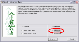
Select the Line-Point 2D alignment and click Next >> to open the 2D-LinePoint dialog box appears.
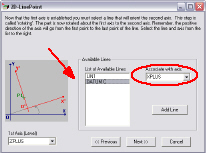
From the List of Available Lines, select DATUM C, and associate it with the XPLUS axis from the Associate with axis drop-down list.
Click Next >> to open the 2D-LinePoint Alignment - Origin dialog box.
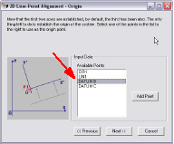
From the list of Available Points, select DATUM B.
Click Next >> to show the Line-Point dialog box.
Click Finish to insert the alignment command into the measurement routine. The DCC (or refined manual) alignment is complete.
Click the +/- (expand/collapse) next to the new alignment in the Edit Window. Notice the alignment steps that were created under the alignment command by the 3 2 1 Alignment Wizard.