CAD and Graphic Setup dialog box - OpenGL tab
The Edit | Graphic Display Window | OpenGL menu option displays the OpenGL tab of the CAD and Graphic Setup dialog box. This allows you to change the OpenGL options that affect the display of the model in solid view mode. To change the part to solid view, see "Setting Up the Screen View" in the "Editing the CAD Display" chapter.
Desktop Settings area
There can be different OpenGL options for each desktop display setting. The Desktop Settings area shows what the current desktop settings are.
Resolution Ratios of Different Monitor Sizes
Wide screen monitors need a 1.6 ratio instead of a 1.3333 ratio used by normal monitors. For example, a resolution of 1200x1600 has a 1.3333 ratio (1600/1200) and works well for a normal-size monitor, while a resolution of 1680x1050 has a 1.6 ratio, good for a wide screen monitor. If you use a wide screen monitor and your screen appears stretched (perhaps your circle features appear as ellipses in the Graphic Display window), use a 1.6 resolution ratio to resolve this problem.
Options area
The Options area displays information about the system's video card:
Video Accelerator - Video card description
Driver version - Video driver version
Driver date - Video driver date of release
Video memory - Amount of video card RAM
OpenGL version - Version of OpenGL supported by the video driver
Hardware accelerated - Displays Yes or No depending on whether graphics rendering is hardware accelerated. Hardware acceleration is much faster than software acceleration.
Antialiasing - The Antialiasing list allows the level of antialiasing by specifying the number of multisamples. 2x antialiasing samples each pixel twice. 4x antialiasing samples each pixel four times, and so on. When antialiasing is enabled, each pixel is sampled multiple times at slightly different locations within the pixel. An average color is computed from these samples to determine the final pixel color. This effectively reduces the model's jagged edges in the Graphic Display window. Higher antialiasing settings produce better visual results at the expense of slower system performance.
The capabilities of your video card determine the antialiasing options. Some graphics accelerators may support 64x antialiasing while others may only support up to 16x, or they may not support antialiasing at all. If your graphics accelerator supports antialiasing, the amount of RAM it possesses and the resolution of your screen determine the default value (with a maximum default value of 4x). If your video card does not support antialiasing, PC-DMIS sets the default to Off.
The High quality transparency check box controls the HighQualityTransparency registry entry. By default, PC-DMIS clears this check box. It only functions if your graphics driver supports OpenGL 4.2 and your video adapter has at least 1 GB of memory.
Tessellation area
The Tessellation area controls the drawn image by setting a tessellation multiplier in the Multiplier Value box. PC-DMIS multiplies the Multiplier Value by the tessellation value for the given CAD system. These values are then used in the generation of the shaded image.
The tessellation value is the default value used to break up surfaces into patches for shading.
The tesselation multiplier updates the Graphic Display window immediately once you click outside of the Multiplier Value box or press Tab to move to a different item on the dialog box.
Modifying this tessellation value affects perimeter scans because PC-DMIS computes the distance around a curved surface edge by adding the segment lengths of a polyline that represents that edge. The tessellation multiplier changes the length of each polyline segment (lower tolerances result in smaller segments). While the actual perimeter points lie exactly on the edge curve, different tessellation tolerances result in small differences in where each point is located along the edge curve.
The size of the CAD data file and the tessellation multiplier
value used affects the amount of memory needed. These both affect the
amount of tessellated facets needed to display the model. The smaller
the tessellation multiplier value used, the more memory needed for the
facets. For large CAD models, this could cause an "Out Of Memory"
error. If this occurs, the current PC-DMIS
session is left in an unstable state and should be terminated.
The default tessellation multiplier value is 1.0. Setting a tessellation
multiplier of 0.1 results in a 10 to 20 percent increase in the memory
required over the default value of 1.0. Decreasing the tessellation multiplier
further to 0.01 results in an additional 50 to 65 percent increase of
memory required.
Pointcloud area
The Pointcloud section determines how PC-DMIS draws a pointcloud (COP) in the Graphic Display window. A COP typically is generated from laser probes that can quickly collect large numbers of points. For more information on pointclouds, see the "PC-DMIS Laser" documentation.
Always visible - This setting applies to Pointcloud Point Colormaps when the Dots, Needles and/or Text options are enabled.
When you enable this option, the Dots, Needles and/or Text for the Point Colormap are visible even if they are lower than the CAD model (negative relative to the CAD face).
When this option is not enabled, PC-DMIS only displays the Point Colormap points and text if they appear in the current view.
Default Display - Sets the default graphical representation of the pointcloud in the Graphic Display window.
The valid options are:
Smooth (default)
Flat
Two sided
The software uses the display setting each time you create a pointcloud feature. For details, see "Pointcloud Graphical Representation" in the PC-DMIS Laser documentation.
Point size - Specifies the pixel size of the points in a pointcloud.
Caliper line thickness - Specifies the thickness of the Caliper gage line, and the connecting line for thickness colormap annotations when the opposing sides are shown. The line thickness options are shown below with the default option selected:
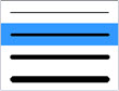
Caliper line thickness options
The line thickness options correspond to (from thinnest to thickest) 1, 3, 5, and 7 pixels.
For details on the Caliper feature, see the "Caliper Overview" topic in the PC-DMIS Laser documentation.
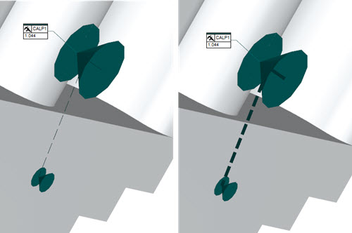
Examples that show the smallest (left) to largest (right) Caliper line thickness options
Sphere Diam - Specifies the size of the thickness annotation points when you select the Show opposing annotation points check box on the Pointcloud Operator or Mesh Operator dialog box when you select the Pointcloud or Mesh Thickness Colormap operator. For details, see "Mesh Thickness Colormap" in the PC-DMIS Laser documentation.