When you create a section cut, PC-DMIS generates a set of curves from where the clipping plane intersects the part. These section cut curves behave like any other curve in the CAD model. You can select and program the section cut curves so that your measurement routine measures them.
Section cut curves are not compatible with versions prior to 2014.1. If you save your measurement routine to a version before 2014.1, the software removes the section cut curves from that measurement routine's associated CAD model.
Creating Section Cut Curves
To create section cut curves (or polyline) from the intersection of the Clip Plane and the CAD:
From the Edit menu, point to Graphic Display Window, and choose Lighting, Materials.
Click the Clip Planes tab.
On your CAD model, click a CAD object.
From the Clip Planes tab of the CAD and Graphics Setup dialog box, select the Enabled check box to mark it.
Adjust the X, Y, Z and I, J, K values as needed.
Adjust the values for the Move clipping plane along above IJK as needed.
Click Apply to set the clipping plane and enable the Create Section Cut Curves button.
Click the Create Section Cut Curves button to create the section cut curves.
Click OK to close the dialog box.
Viewing Section Cut Curves
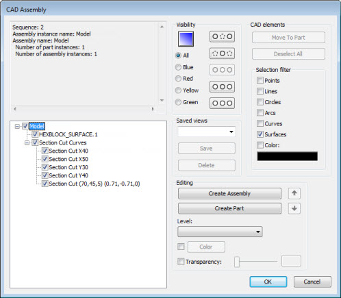
To view the section cut curve from the assembly tree view of the CAD Assembly dialog box:
From the Edit menu, point to Graphic Display Window, and choose CAD Assembly to open the CAD Assembly dialog box.
From the assembly tree view, click the plus sign to expand the list of assembly components.
At the root of the assembly tree view is an assembly component named "Section Cut Curves". Click the plus sign to expand it and show the section cut curves.
The items that begin with "Section Cut" are followed with some descriptive text:
If the clipping plane is aligned with a trihedron axis, the descriptive text is that axis's character followed by the position of the plane along that axis. For example, a clipping plane located at X = 20, Y = 10, Z = -4 has an entry of "Section Cut Z-4"
If the clipping plane is not aligned with a trihedron axis, the descriptive text contains both the plane point and the vector values. For example, a clipping plane located at X = 80, Y = 40, and Z= -12 and a vector of 0.87, 0.0, 0.50 has an entry of "Section Cut (80,40,-12) (0.87,0,0.50)".
Mark or clear the check box next to each section cut to show or hide the curves in the Graphic Display window.
Example of the CAD Assembly dialog box with several created section cut curves