Viewing
All Path Lines
Viewing
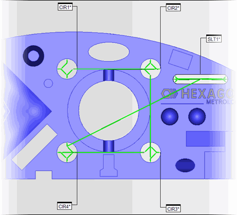
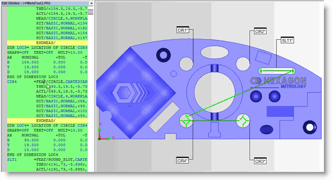
All Path LinesPC-DMIS can generate colored lines on the CAD model in the Graphic Display window that show the path your probe will take during execution as it measures marked features. These lines are called path lines. Path lines help you preview the path your probe will take and troubleshoot possible collision areas.
The software only generates the probe's path lines for features that follow a MODE/DCC command. If your measurement routine doesn't have a MODE/DCC command, you won't see any path lines.
The Animate Path, Regenerate Path, Optimize Path, and Collision Detection options are not available for Portable devices.
Viewing
Path Lines from a Cursor's Position
Viewing
Path Lines for a Range of Selected Items
You can use the Path toolbar on the QuickMeasure toolbar (View | Toolbars | QuickMeasure) to work with common path line options. For more information, see the "CMM QuickMeasure Toolbar" topic in the PC-DMIS CMM documentation.
More: