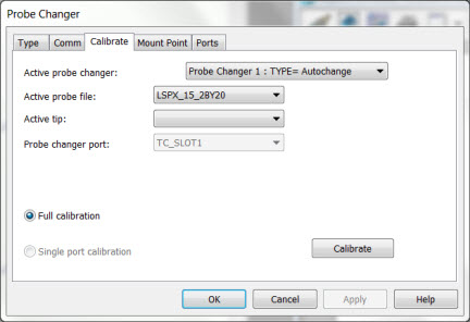
To open the Calibrate tab in the Probe Changer dialog box, select Edit | Preferences | Probe Changer.
Probe Changer dialog box - Calibrate tab
Before you begin the calibration process, consider the following:
You must choose the probe changer type from the Type tab.
Before you start this process, verify that the stylus has been calibrated. For more information, see "Defining Probes" in the "Defining Hardware" chapter.
The rack should be squared to one of the CMM's axes.
Generally, you should physically align probe changers along one of the machine’s axis. However, for the TP20, TP200, and SP600 Probe Changers, this isn't required. For these probe changers, the rack still needs to be level, but you can now rotate it so that the length of the rack is no longer aligned along a machine axis.
Active probe changer
From this list, select the probe changer to calibrate. For more information, see "Type Tab".
Active probe file
From this list, select a probe to use for the calibration process.
Active tip
From this list, choose a tip configuration for the probe that you selected.
Probe changer port
This list works in conjunction with the Single port calibration option. It enables you to choose a single port to calibrate. These dialog box items remain unavailable for selection until you define a probe changer that supports calibrating an individual port.
Full calibration
If you select the Full Calibration option, PC-DMIS measures the entire probe changer. This is the most often used method of calibration, and for some it is the only method that is available. It is recommended that the operator use the full calibration method.
Partial calibration
This option only calibrates a portion of the probe changer. This option only appears for the changer types that support it.
Single port calibration
Some probe changers, such as the ACR1, enable you to measure only a single port after a successful full calibration. The Single port calibration option only appears for the changer types that support it.
Calibrate Button
Before you can use your probe changer, you must define the changer's port locations through the appropriate probe changer calibration procedure. The following topics discuss the calibration processes for several probe changers. If you have a probe changer type that is different from the ones discussed, use the calibration process for the FCR25 Probe Changer as a guide. It should be similar enough for all supported types.
Calibrating the FCR25 Probe Changer
Calibrating the ACR1 Probe Changer
Calibrating the ACR3 Probe Changer
Calibrating the CW43 Probe Changer
Calibrating the HR-MP (used with TM or THD) Probe Changer
Calibrating the HR-MS or HR-X1 Probe Changer
Defining the I++ Client Probe Changer
Calibrating the LSPX3 / HR-X (HR-X3-P) Probe Changer
Calibrating the LSPX3SF / HR-X (HR-X3-P-SF) Probe Changer
Calibrating the LSPX5 / HR-XS Probe Changer
Calibrating the SCP600 Probe Changer
Calibrating the SCR200 Probe Changer
Calibrating the SP600 Probe Changer
Calibrating the TESASTAR-PR / HR-P Probe Changer
Calibrating the TESASTAR-R / HR-R Probe Changer
Calibrating the TP20 Probe Changer