Step 3 - Define the Ports
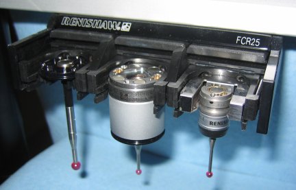
The example described below has a PA25-SH insert in port 1(left), NO INSERT in port 2 (middle), and a PA25-20 insert in port 3 (right).
To define the ports of your FCR25 Probe Changer, do the following:
Select the Ports tab in the Probe Changer dialog box (Edit | Preferences | Probe Changer).
In the Active probe changer list, select TYPE=FCR25.
In the Number of ports box, in multiples of three, specify the number of ports for your FCR25 Probe Changer. PC-DMIS then lists the specified number of ports as "ports" (for example, port 1, port 2, port 3, and so forth). Until you define the ports, PC-DMIS lists the "port" entries as "UNDEFINED". You must define all of the ports in the rack before you start.

Ports tab with undefined ports
Select a port from the list, and click Edit Port Data. The Probe Changer Port Data dialog box opens.
In the Port type list, select NO INSERT, PA25-SH, or PA25-20.
You may specify the XYZ values for the center position of the port or leave those values empty. In any case, PC-DMIS automatically populates these values upon successful calibration. See "Step 9 - Review Calibration Results".
To save the changes to the port data, click OK.
Repeat steps 4 through 6 for all ports in your changer.
Ports tab
To save your changes, click Apply.
The next step prepares you to calibrate the probe changer.