
Step 4 - Define the Ports
The final step prior to the actual calibration of the TESASTAR-R / HR-R Probe Changer is to define the number and configuration of the ports on the probe changer. For an example of how to define ports, see "Example of Defining Ports" at the end of this topic.
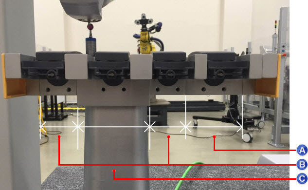
The TESASTAR-R / HR-R rack has four types of ports:
Types of ports:
A - MOD .65: Has a circular
port
B - HD: Has a port with two pins for changing
the HD components
C - Center Post: Has a circular port and is mounted
on the probe changer post
D - MOD .40: Has a circular port
Another image of the ports on the TESASTAR-R / HR-R rack appears below:
Types of ports:
A - MOD .65
B - MOD .40
C - Center Post
TKJ extension-only ports have an extension-only location associated with each empty HD extension.
Defining the Number of Ports
Select the Ports tab in the Probe Changer dialog box (Edit | Preferences | Probe Changer):

Probe Changer dialog box with undefined ports
In the Active probe changer list, select TYPE=TESASTAR-R.
In the Number of ports box, type the number of ports that you want to define. This should match the number of physical ports on the probe changer.
Click Apply to store this parameter.
After you define the number of ports, you need to define the configuration of each port. You can do several different configurations depending on the size and location of the port hardware. For the proper configuration of each port, consult your probe changer's documentation.
Select the port item in the list and then click Edit Port Data to display the Probe Changer Port Data dialog box:

Probe Changer Port Data dialog box
In the Probe Changer Port Data dialog box, if Port type shows UNDEFINED, select the appropriate type for the port.
Click OK to return to the Probe Changer dialog box.
Define any remaining ports. As you define each port type, the port description in the list shows the "(changes pending)" text appended.
Click Apply. The text is removed on all of the ports.

Probe Changer dialog box with all ports defined
If you plan to use any of the ports to hold probe extensions, you need to define them in this step before you proceed. Ports that hold extensions require additional steps in the calibration process where you need to take additional hits on the datum sphere with and without the extension.
You are now ready to begin calibration.
Example of Defining Ports
The example below shows seven defined ports:

Example of Probe Changer dialog box with seven defined ports
In this example, ports 1 and 7 are HD extension-only ports. Ports 3 and 5 are TKJ extension-only ports. The one in port 3 has a 90-degree rotation of the bottom joint.
Note the following:
If you combine HD extensions with regular TKJ extensions by loading an HD extension and then use it to load a TKJ extension, and if you have more than one HD port with an extension that can be used with the TKJ extension, the incremental offset gained by loading that TKJ extension varies slightly depending on which HD extension you used it with.
If you use multiple HD extensions with TKJ extensions, the calibration requires that you attach and measure the TKJ extension with each HD extension. After calibration, there is a separate XYZ for the "With empty extension" result for each HD extension it was used with. You can select which result to view or edit by selecting the port associated with the HD extension it was used with.
If you do not have more than one HD extension, or if you have not yet calibrated to allow the multiple results to become available, no selection is available.
If you select port 3 (a TKJ extension-only port) and then click the Edit Port Data button, the Probe Changer Port Data dialog box appears. In the Prior attached extension for empty extension XYZ list, you would select the port with the results you want to view.
The image below shows the results with the HD extension from port 1:

Example of Probe Changer Port Data dialog box
The image below shows the results if you use the same TKJ extension with the HD extension in port 7:

Example of Probe Changer Port Data dialog box
The differences in the extension-only location for the port 1 and port 7 scenarios above are relatively small. However, they are significant for correct positioning for probe change purposes.
The next step starts the calibration process.