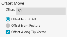
Offset Move area
(This item exists in the Move Point dialog box, accessible from Insert | Move | Move Point or Operation | Move To.)
The Offset Move area lets you create move points offset from a selected CAD point or from a selected feature's centroid.
Offset - This box determines the offset distance from the CAD point or feature centroid. The unit of measurement is the same as your measurement routine. The default is 50 mm or 1.96 inches.
Offset from CAD - If you select this option and click on the CAD, PC-DMIS computes the move point at the selected point on the surface and offsets the move point by the specified distance.
If you clear the Offset Along Tip Vector check box, PC-DMIS creates the move point offset away from the surface along the surface's normal vector.
If you select the Offset Along Tip Vector check box, PC-DMIS creates the move point in the direction of the probe tip's vector.
Offset from Feature - If you select this option and click on a feature, PC-DMIS computes the move point by the offset distance at the feature's centroid.
If you clear the Offset Along Tip Vector check box, PC-DMIS creates the move point offset in the direction of the feature's vector.
If you select the Offset Along Tip Vector check box, PC-DMIS creates the move point in the direction of the probe tip's vector.
Offset Along Tip Vector - You can select this check box to offset the move point along the active tip's vector. If you clear the check box, PC-DMIS offsets the move point along either the CAD's surface vector or along the feature's vector.
Different feature types have different vectors. When the software offsets along a vector of the feature, PC-DMIS uses the vector that gives the best representation of being "outward" from the surface of the part.