At this point, you have a probes for both arms defined. You've also defined the orientation between the arms. Now, you need to map available wrist angles you'll be using.
Check to see the ability to use wrist maps is already enabled. You can do this by accessing the Probe Utilities dialog box for a probe that has a wrist. If you see the Use wrist map if available check box, this functionality is enabled. If you don't see it, check to ensure that the DeaWrist registry entry is 1.
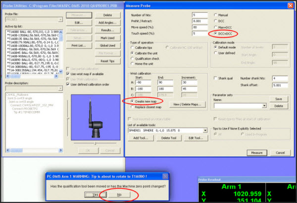
Access the Measure Probe dialog box (Insert | Hardware Definition | Probe | Measure button) for PROBE1 and set these options and values:
In the Type of operation area, choose Calibrate the unit.
In Calibration mode, choose User defined.
The boxes in the Wrist calibration area should now be editable.
Choose DCC + DCC. This is needed for long extensions.
For the A angle values (the probe's pitch), define the following: For Start A, type -90; for End A, type 90; and for Increment, type 30.
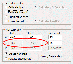
In the B angle values (the probe's roll), define the following: For Start B, type -180; for End B, type 180; and for Increment, type 45. Note that you cannot adjust the A and B angles. You can only adjust the increment.
B angles are disabled in 2012 and later
Choose Create new map.
For increased precision in your calibration, you can decrease the increment value. This increases the time. For shorter extensions, the value of 30 and 45 is a medium value.
For List of available tools, choose SPHERE1.
Click Measure.
When PC-DMIS asks if the qualification tool has been moved or the machine zero point changed, click No.
Arm 1 starts to measure all the positions defined in the dialog box. Generally, this lasts approximately an hour, but it depends on the speed of the machine and the size of your probe's extension. A shorter extension is faster.
Dialog boxes showing the settings used
The next step provides information on mapping the wrists of Arm 2 using SPHERE2.