In this Topic Hide
The Feature Control Frame Editor
The Zone, Feature, and Characteristic Section
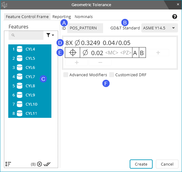
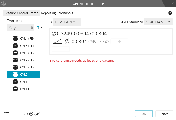
The Feature Control Frame tab of the Geometric Tolerance dialog box is where most of your editing takes place. A typical position tolerance might look like this in the dialog box:
ID - This box defines the dimension's ID. In the picture above, it was edited to say POS_PATTERN. For the position tolerance, the ID defaults to something like FCFLOC1, 2, 3... etc. if you do not edit it.
GD&T Standard - This list defines the standard to use in the tolerance. It should match the standard used by your print. We support prints based on ASME Y14.5 and ISO 1101; the specific versions of the standards we support (including supporting standards like ISO 5459) are detailed in the "Introduction to Geometric Tolerances and Feature Control Frames" topic.
Feature List - This list shows the available features for the type of geometric tolerance. For more information, see "The Feature List" below.
Size Tolerance Editor - The first row in the tolerance editing pane shows the size and plus and minus tolerance information. For more information, see "The Size Tolerance Editor" below.
Feature Control Frame Editor - The second row in the tolerance editing pane is main editing area. For more information, see "The Feature Control Frame Editor" below.
Additional Options - This area of the dialog box contains advanced and other options for your tolerance. For more information, see "Additional Options" below.
The first thing to do when you start to create a geometric tolerance is to select the considered feature or features. When the dialog box opens, no features are selected. Every feature in the measurement routine that is allowed for the tolerance type is shown. If you don't see an expected feature, make sure your pointer in the Edit window is below that feature before you access the Geometric Tolerance dialog box.
In large routines with many features, you may find it helpful to search for a feature with the search bar.
After you select one feature, PC-DMIS filters the feature list so that only similar features or features with the same characteristics are shown (such as cylinders with the same diameter). You may then select additional features at that point.
The first row of the tolerance editing pane is the Size Tolerance Editor. It is available when your considered features are features of size (cylinders, circles measured on a surface, spheres, or widths) and your geometric tolerance type allows size tolerances.
The Size Tolerance Editor looks like this:
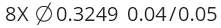
This line contains several types of information and two controls:
8X means there are eight considered features; it is not visible when there is only one considered feature. You cannot edit the symbol.
 means the features are cylinders
or circles measured on a surface. The symbol is different for different
kinds of features of size. Spherical features have a
means the features are cylinders
or circles measured on a surface. The symbol is different for different
kinds of features of size. Spherical features have a  symbol. Width features
do not have a symbol. You cannot edit the symbol.
symbol. Width features
do not have a symbol. You cannot edit the symbol.
The first number after the above symbol is the nominal size. You cannot edit this value because the geometric tolerance command requires all features to have correct nominals. The nominal size comes from the feature's THEO (theoretical) size.
The second number, the one before the forward slash (/), is the plus tolerance for the feature's size. You can edit it. The upper limit of size is equal to the nominal size plus the plus tolerance.
The third (and final) number, the one after the forward slash (/), is the minus tolerance for the feature's size. You can edit it. The lower limit of size is equal to the nominal size minus the minus tolerance, when the Minus tols show negative check box in the Dimension tab of the Setup Options dialog box is cleared. If you mark Minus tols show negative, then the lower limit of size is equal to the nominal size plus the minus tolerance. You may prefer to mark this check box to make the size tolerance look like your print. For information on this check box, see the "Minus Tols Show Negative" topic in the "Setting Your Preferences" chapter. This check box exists so you don't have to type the minus sign for minus tolerances.
The most complex part of the tolerance editing pane is the Feature Control Frame Editor. It looks like this:
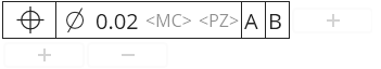
There are several parts to this editor, which are detailed below.
The tolerance symbol shows up in the left-most box of the Feature Control Frame Editor. It shows the symbol for the tolerance type you chose. You can change the symbol to change the tolerance type. You click the tolerance symbol to choose another valid geometric type for the features that you selected; the other symbols appear in a drop-down window.
The zone, feature, and characteristic section of the feature control frame includes the tolerance zone shape, the tolerance value, and any tolerance modifiers. Therefore, this section contains several controls. Their availability varies depending on what tolerance type and what considered features are chosen.
The tolerance zone shape symbol is first.
It is for diametric zones,
for spherical zones, and blank for planar zones (and for radial
arc and perpendicular to radial zones). If you click the symbol,
you can edit which symbol appears, but the only available symbols
are those that make sense for the considered features and the
tolerance type you chose.
The tolerance value is second. It is a number (0.02 in the above picture). You may edit it to any positive value.
When it makes sense for your considered
features and tolerance type, the material condition control is
next. It appears as ![]() when there is no material condition modifier. That means the feature
is referenced at regardless of feature size (RFS). When there
is a maximum material condition (MMC) modifier, it appears as
when there is no material condition modifier. That means the feature
is referenced at regardless of feature size (RFS). When there
is a maximum material condition (MMC) modifier, it appears as
 .
When there is a least material condition (LMC) modifier, it appears
as
.
When there is a least material condition (LMC) modifier, it appears
as  .
Click the
.
Click the ![]() , , or to switch between no
material condition modifier, the MMC modifier, or the LMC modifier.
, , or to switch between no
material condition modifier, the MMC modifier, or the LMC modifier.
When it makes sense for your considered
features and tolerance type, the projected zone control is next.
It appears as ![]() when there is no projected zone
modifier. When there is a projected zone modifier, it appears
as
when there is no projected zone
modifier. When there is a projected zone modifier, it appears
as  with a projected length number that immediately
follows it, like this:
with a projected length number that immediately
follows it, like this:  . Click the projected
length number to edit it. Click the
. Click the projected
length number to edit it. Click the ![]() or
to switch between no projected zone modifier or the projected
zone modifier.
or
to switch between no projected zone modifier or the projected
zone modifier.
When it makes sense for your considered
features and tolerance type, the tangent plane control is next.
It appears as ![]() when there is no tangent plane
modifier. When there is a tangent plane modifier it appears as
when there is no tangent plane
modifier. When there is a tangent plane modifier it appears as
 .
Click the
.
Click the ![]() or to switch
between no tangent plane modifier or the tangent plane modifier.
or to switch
between no tangent plane modifier or the tangent plane modifier.
For profile tolerances, the profile modifier
control appears after the tolerance. It appears as ![]() when there is no profile
modifier. When there is an ASME unequal disposition modifier,
it appears as
when there is no profile
modifier. When there is an ASME unequal disposition modifier,
it appears as  with an unequal disposition
distance that immediately follows it, like this:
with an unequal disposition
distance that immediately follows it, like this:  . When there is an ISO
unequal disposition modifier, it appears as
. When there is an ISO
unequal disposition modifier, it appears as  with an unequal disposition distance that immediately follows
it, like this:
with an unequal disposition distance that immediately follows
it, like this:  . When there is an ASME dynamic
profile modifier, it appears as
. When there is an ASME dynamic
profile modifier, it appears as  . When there
is an ISO offset zone modifier, it appears as
. When there
is an ISO offset zone modifier, it appears as  .
.
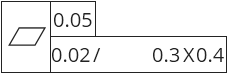
For per-unit straightness and per-unit profile of a line, you can edit the per-unit length right after the / symbol, as shown in the lower segment below:
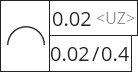
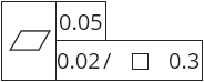
For per-unit flatness, to the right of
the / symbol, there is the unit shape control. It appears blank
when the unit is rectangular, and it appears as a square  when the unit shape is square. Rectangular unit shapes give you
a length and a width to edit, while square unit shapes give you
only a length. Click the blank or the square to switch between
the two.
when the unit shape is square. Rectangular unit shapes give you
a length and a width to edit, while square unit shapes give you
only a length. Click the blank or the square to switch between
the two.
Rectangular unit shape |
Square unit shape |
The datum section of a feature control frame (or of a tolerance indicator) is just to the right of the zone, feature, and characteristic section. This consists of zero to three boxes. Each box contains a datum reference (potentially a common datum reference) and zero or more datum modifiers.
The + button to the right of the Feature Control Frame Editor lets you add datums:
When you click this button, PC-DMIS adds a pre-defined datum to your feature control frame. Each time you click it, it adds a pre-defined datum that has not already been added to this feature control frame.
If no pre-defined datum exists that has not already been added to the feature control frame (or if no pre-defined datums exist at all), then this button shows the Datum Definition dialog box. You can use that dialog box to define a datum. (For information on the dialog box, see "Dialog Box Usage and Command Syntax".) This inserts a datum definition command just above your geometric tolerance command. However, the new datum is not automatically selected for you. This means you need to click the add-datum button (+) again to select the new datum reference.
To change a datum reference inside a datum box, click the datum reference. A drop-down menu appears from which you can choose a new reference:
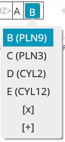
From the drop-down menu, you can select a pre-defined datum reference, where the feature name is shown in parentheses next to the datum reference (datum patterns only show one feature name, and common datums don't show any feature names).
If you choose the  option, the datum box is
deleted.
option, the datum box is
deleted.
If you choose the  option, the Datum
Definition dialog box opens up, so that you can define a new datum.
(For information on the dialog box, see "Dialog
Box Usage and Command Syntax".) However, the new datum is not
automatically selected for you. This means you need to click the old datum
reference from the datum box and then choose the new datum reference.
option, the Datum
Definition dialog box opens up, so that you can define a new datum.
(For information on the dialog box, see "Dialog
Box Usage and Command Syntax".) However, the new datum is not
automatically selected for you. This means you need to click the old datum
reference from the datum box and then choose the new datum reference.
To the right of each datum reference, there are the controls for any datum modifiers.
When it makes sense for your datum
and tolerance type, the material boundary control is first.
It appears as ![]() when you reference the datum
without a material modifier. That means the datum is referenced
at regardless of material boundary (RMB). When there is a
maximum material boundary (MMB) modifier, it appears as .
When there is a least material boundary (LMB) modifier, it
appears as . Click the
when you reference the datum
without a material modifier. That means the datum is referenced
at regardless of material boundary (RMB). When there is a
maximum material boundary (MMB) modifier, it appears as .
When there is a least material boundary (LMB) modifier, it
appears as . Click the ![]() ,
,
or
to switch between no material modifier, the MMB modifier,
or the LMB modifier.
,
,
or
to switch between no material modifier, the MMB modifier,
or the LMB modifier.
When a datum is referenced at MMB or
LMB, and you marked the Advanced Modifiers
check box, you can specify a material boundary size. This
is not
the nominal size of the datum feature, nor is it the maximum
or minimum material condition size of the datum feature. For
more information about material boundary sizes, see the "Determining
the Size of the Material Boundary" sub-topic of the
"How PC-DMIS
Solves and Uses Datums" topic. For datum cylinders,
this modifier looks like this if you haven't specified a material
boundary size: ![]() .
After you specify a material boundary size, the modifier looks
like this:
.
After you specify a material boundary size, the modifier looks
like this:  , with whatever size you specified.
To remove a specified material boundary size, delete the size
value and then press tab to move off of the modifier.
, with whatever size you specified.
To remove a specified material boundary size, delete the size
value and then press tab to move off of the modifier.
When the datum is a secondary or tertiary
datum, and you marked the Advanced Modifiers
check box, the translation control appears next. It appears
as ![]() when the datum is referenced without
a translation modifier. When there is a translation modifier,
it appears as
when the datum is referenced without
a translation modifier. When there is a translation modifier,
it appears as ![]() . Click the
. Click the ![]() or
or ![]() to switch between
no translation modifier and the translation modifier.
to switch between
no translation modifier and the translation modifier.
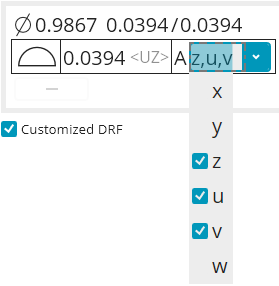
If you marked the Customized DRF check box, you can specify custom degrees of freedom for each datum. This check box shows the default degrees of freedom constrained by each datum, in a text form like [z, u, v]. If you click the degrees of freedom, you can mark or clear additional degrees of freedom from a drop-down list that looks like this:
This check box is under the tolerance editing pane, and it looks like this:
Position and profile ASME tolerances have an Advanced Modifiers check box. If you mark this check box, PC-DMIS enables access to translation modifiers and specified material boundary modifiers. It also removes access to customized datum reference frames. This check box is cleared by default because most users do not need these advanced modifiers.
This check box is under the tolerance editing pane, and it looks like this:
Position and profile ASME tolerances have a Customized DRF check box. If you mark this check box, PC-DMIS enables access to customized datum reference frames, and removes access to advanced datum modifiers. This check box is cleared by default because most users do not need customized datum reference frames.
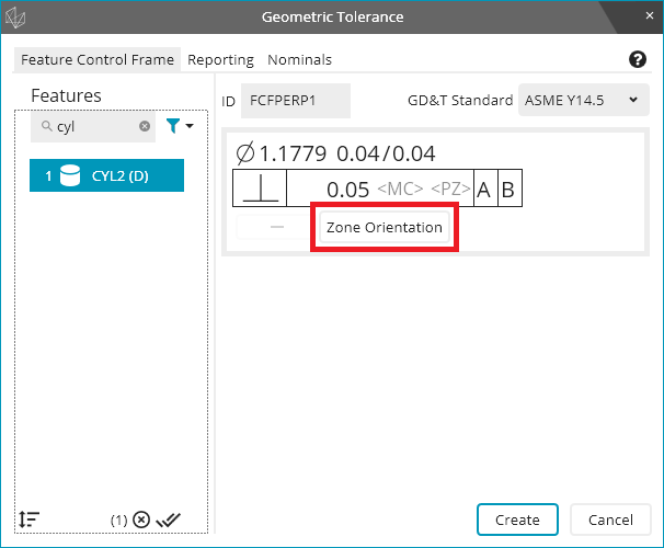
When it makes sense for the chosen tolerance zone shape symbol, tolerance type, and considered features, the Zone Orientation button becomes visible:
If you click the Zone Orientation button, the Tolerance Zone Orientation dialog box appears. This dialog box allows you to control the orientation of the tolerance zone:
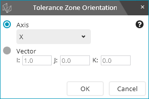
The Tolerance Zone Orientation dialog allows you to define the surface normal vector of the planar tolerance zone, or the axis vector of the diametric tolerance zone. The Axis drop-down list is for when the vector is along the X, Y, or Z axes (respectively). Alternatively, you can select an arbitrary vector with the Vector option and boxes under it.
As an example, if a position tolerance controls the X component of the position (planar tolerance zone), the tolerance zone surface normal vector should be X.
The zone orientation vector is always in part coordinates, never datum reference frame coordinates. It is also always normalized (has length equal to 1) and always compatible with the orientation of the considered feature.
To select a polar tolerance zone (radial arc or perpendicular to radial), click the Zone Orientation button, and from the Axis drop-down list, select Radial Arc or Right Angle to Radial.
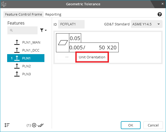
Per-unit flatness tolerances have square or rectangular units, as described in the "Flatness" topic. The geometric tolerance command needs to know how to orient the unit on the planar surface. You can enable per-unit flatness with the plus sign that adds the lower segment:

The Unit Orientation button becomes visible:
If you click the Unit Orientation button, the Unit Orientation dialog box appears. This dialog box allows you to control the unit orientation:
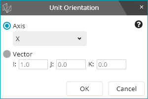
The Unit Orientation dialog box allows you to define the unit's orientation vector. For more information, see "Flatness_Per_Unit" in the "Flatness" topic.
This check box is under the tolerance editing pane, and it looks like this:
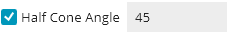
For circular runout tolerances on circles, the geometric tolerance command allows you to treat the circle as a cross section of a cone instead of a cross section of a cylinder. To do this, you can select the Half Cone Angle check box and then type an angular value for the cone half angle. For more information, especially the meaning of the sign of the cone half angle, see "Circular Runout".
The Conicity check box is under the tolerance editing pane, and it looks like this:

As discussed in the "Circularity" topic, PC-DMIS can evaluate circularity tolerances on cones as true circularity or as conicity. By default, it is evaluated as true circularity, but you can change it to conicity by selecting this check box.
These left and right options appear inside the tolerance editing pane if your considered features are slots:
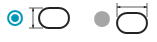
The left option considers the slot in a widthwise fashion. The size of the slot is its width, and the tolerance zone controls the slot's position in the width direction.
The right option considers the slot in a lengthwise fashion. The size of the slot is its length, and the tolerance zone controls the slot's position in the length direction.
These options appear inside the tolerance editing pane if you have concentricity or symmetry tolerance with ASME:

For concentricity and symmetry ASME tolerances, when the considered features have surface data, PC-DMIS can interpret them in terms of the Median Points or in terms of the Axis. You can choose the desired option to control the interpretation. Median Points is the default.
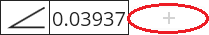
Underneath the Feature Control Frame Editor, there are + and - buttons to add and remove segments, respectively. When it does not make sense to add any more segments, the + button is not available.
The buttons look like this:
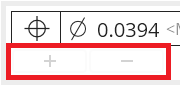
You can use these buttons to construct composite position tolerances, composite profile tolerances, and per-unit tolerances.
Underneath all of these feature control frame options, PC-DMIS shows error messages, warnings, and other informational messages. For information on how to resolve error or warning messages, see "Troubleshooting Error Messages and Warnings".
Error messages - Error messages show up in red.
When there is an error message, you cannot click Create or OK in the dialog box.
Error messages look like this:
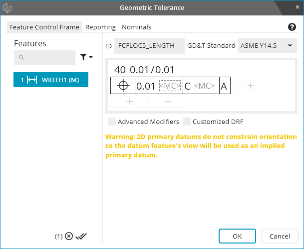
Warning messages - Warning messages show up in yellow.
When there is a warning message, you can press Create or OK in the dialog box.
Warning messages look like this:
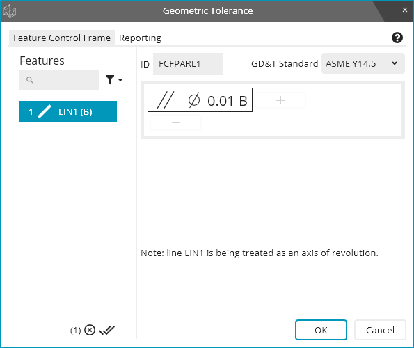
Interpretation messages - Interpretation messages show up in black.
Interpretation messages appear when you use a constructed line feature as a datum feature or as a considered feature. The message lets you know whether PC-DMIS interprets the feature as a line on a surface (such as a cross section of a planar surface) or as an axis of revolution (such as a surfaceless axis). For more information about what line types are considered a line on a surface, versus what line types are considered an axis of revolution, see "Feature Types With and Without Surface Data".
Interpretation messages look like this:
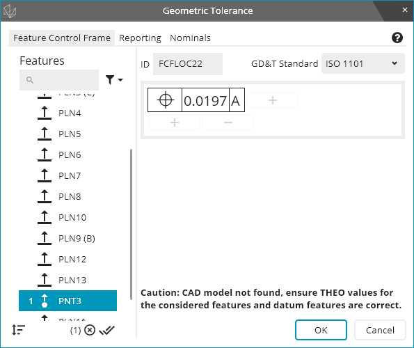
CAD Warning messages - There is an additional type of warning message that appears in black just above the main command buttons on the dialog box.
If you do not have a CAD model, PC-DMIS cannot ensure that your program THEO values are all correct. The Geometric Tolerance dialog box shows a warning message that cautions you to ensure your THEO values are all correct. You can still click Create or OK in the dialog box.
This CAD warning looks like this: