 Hexagon
test block (Hexblock_Wireframe_Surface.igs).
Hexagon
test block (Hexblock_Wireframe_Surface.igs).This topic walks you through a very basic tutorial that will result in you creating a simple custom report. This should give you a basic overview of how custom reports are created within the Custom Report Editor and how they interact with existing label templates so you can later create and use your own custom reports.
Before you begin this tutorial, create a simple measurement
routine that has four measured circles on a simple part and four Circularity
dimensions, one for each circle. This tutorial uses the  Hexagon
test block (Hexblock_Wireframe_Surface.igs).
Hexagon
test block (Hexblock_Wireframe_Surface.igs).
Create a measurement routine that measures four circles, similar to this.
Click on the links below to expand or collapse each step of instructions as needed. Some steps may also include a demo video of that step. For best results, maximize your help viewer before you view any videos.
Step
1: Setting Up the Work Environment
In this tutorial you will use the Edit window in Summary mode along with the Custom Reporting Editor.
Select File | Reporting | New | Custom Report from the menu bar to show both the Custom Report Editor and Summary mode next to it.
You can also create a new
report from the Custom Report Selection dialog
icon ( ) on the Report window's Reporting
toolbar. From the dialog box that appears, click Blank
Report and then Open to create the
blank report.
) on the Report window's Reporting
toolbar. From the dialog box that appears, click Blank
Report and then Open to create the
blank report.
To hide any unused toolbars, right-click on the toolbar area and remove them.
To hide any unused PC-DMIS windows, select the open window from the View menu. Keep the Edit window open.
To maximize the Custom
Report Editor, click the maximize button ![]() in the upper right corner of the editor's window. You should see
the words "CUSTOM" on the background of the editor.
in the upper right corner of the editor's window. You should see
the words "CUSTOM" on the background of the editor.
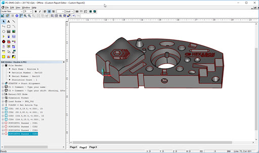
Drag the Edit window
underneath the Custom Report Editor's Object
Bar. Your work environment should now look something like
this:
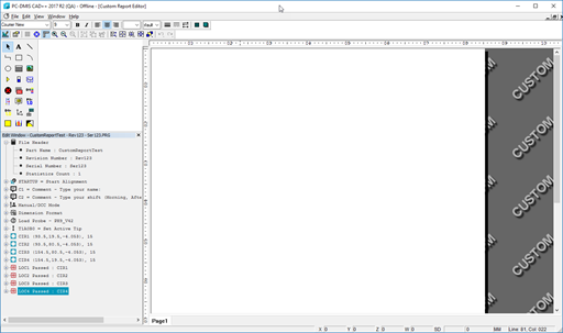
When working with the Custom Report Editor, you may find it helpful to hide your usual PC-DMIS toolbars and windows, thereby freeing up some screen space. If you work frequently with this editor, you may want to create a stored screen layout for it. For information on layouts, see the "Window Layouts Toolbar" topic in the "Using Toolbars" chapter.
Step
2: Dragging, Dropping, and Positioning Objects
In this step, you will drag the report items into the Custom Report Editor.
From the Edit window in Summary mode, select File Header, and drag it out onto the editor. You will notice a transparent image of that item's icon as you drag it out onto the work area.
Release the mouse button. PC-DMIS creates a File Header object in the editor.
Drag and drop CIR1 and CIR2 onto your report. Don't worry about positioning them properly. For now, just drop them into any empty space on the first page of the report.
In the Report Editor, select the File Header object already in your report, and drag it to a place near the top of the report and center it horizontally on the page.
Next, select the label object for CIR1, and drag it so that the top edge is just under the bottom edge of the File Header object. Try to align their left sides as well.
Repeat this step for CIR2.
Now, drag the CIR3 feature from the Edit window to the bottom of the label used for CIR2. Notice that as you move your mouse over the various labels already in the editor, green handles appear around the labels. When the blue arrow appears just below CIR2, release the mouse. The feature is dropped into the editor below CIR2, and the label object for it becomes automatically aligned with the object above it.
Repeat the above step for CIR4, attaching it just below CIR3.
Select File | Save. A dialog box will appear, which allows you to save your report. Choose any name and click Save.
Your Custom Report Editor should look something
like this:
In this step, you will work with multiple pages. You will add two additional pages and modify one page to support a different page size. Then you will rearrange the pages.
In the Report Editor, at the bottom of the page, right-click on the Page1 tab and select Add Tab. A new page appears, called Page2.
Right-click on that page. The Properties dialog box appears.
Change Height to 850, and press the Tab key.
Change Width to 1100, and press the Tab key. Changing these two properties essentially formats the page for Landscape printing.
Create a third page, Page3.
Right-click on Page2, and click Move Right. Notice how this moves the Page2 tab to the right of Page3.
Right-click on Page3, and click Move Left. Your pages are now reordered to show Page3, followed by Page1, followed by Page2. In this way, you can rearrange your pages.
Save your report.
Your report now has three pages, and their order has been changed.
Step
4: Dropping onto Other Objects
This step demonstrates how you can replace existing label objects with new label objects and how to use the CADReportObject inside a custom report.
In the Custom Report Editor, select the Page1 tab. To replace any object in your report, drag and drop any other item of a similar type on top of it. For example, you can drop any item that uses labels on top of any existing label in your editor.
Select the label in your report for the CIR1 feature. You should already have four Circularity dimensions. If not, create them now, one for each circle feature.
Drag the Circularity
dimension for the CIR1 feature from your Edit window and drop
it on top of the feature label already in your report editor for
CIR1, like this:
Notice that the label object is updated with a new label object.
If the updated object moved, reposition it.
Drag the other dimensions on top of their respective feature labels in the editor. PC-DMIS updates all the labels accordingly, so that they look something like this:
Report Editor Now Showing the Four Dimension Labels
Now, click on the Page2 tab. Drag a CADReportObject from the Object Bar onto that page, and size it so it fills the page.
Drag the four dimensions one at a time on top of the CADReportObject. For this object, notice PC-DMIS does not replace it with a label object for the dimension. Instead, PC-DMIS automatically creates the appropriate labels and leader-lines on top of the CADReportObject for the dimensions.
Save your report.
Page1 now has dimension labels instead of feature labels, and the CADReportObject in Page2 should look something like this:
In this step, you will insert a GridControlObject and get it ready to display values from the Edit window.
Click on the Page3 tab.
Click on the GridControlObject icon, and drag the object onto the page.
Access the Properties dialog box, and set NumRows to 8 and NumCols to 3.
In the first row, the middle cell, double-click, and then type "Nominal". In the right cell, do the same, and type "Measured".
Starting with the first row, and first column, and then moving down through the other rows, type "X", "Y", "Z", "I","J" ,"K", and "Diameter". This fills in rows 2 through 8 in column 1. Your GridControlObject should look like this:
A GridControlObject with Static Text
Remember when typing information into a cell, you must click in another cell or press the Tab key for the value to actually be displayed.
Double-click on the item to type the expression in the cell. This cell dynamically displays the data which means the information is not hard coded. If the value changes, PC-DMIS updates the data in your report to match.
Looking at the Data Item's Expression
Finally, apply some text and background formatting of your choice to row 1 and column 1, and then save your report. The GridControlObject should look similar to this:
A Sample GridControlObject
containing Data Items
Select File | Close to close the Custom Report Editor.
Your values may differ based on the part and circles measured.
Step
6: Viewing, Updating, and Printing your Report
This final step explains how to load your custom report into the Report window, how to view it, how to update a report from a measurement routine that changes, and finally how to print it.
Select View | Report Window to access the Report window.
From the Report window's
Reporting toolbar, select Custom
Report Selection Dialog .
A dialog box appears and shows all custom reports.
Select your report and click Open. Your report appears in the Report window.
Next, you will update your report. Select File | Reporting | Edit | Custom Report. A dialog box appears and shows all the reports you've created for your current measurement routine.
Select your report and click Open. Your report opens inside the Custom Report Editor.
Go ahead and make any change to your report in the editor, and then save your report again.
To get the newly-updated report to appear in the Report window, re-execute your measurement routine, or click the Redraw icon from the Reporting toolbar.
Finally, you need to print your report. Select the File | Printing | Report Window Print Setup menu item. The Output Configuration dialog box appears.
Select the Report tab. In the Output Options section, mark the Printer check box to send the report to your printing device.
From the Report window's Reporting toolbar, click the Print icon. PC-DMIS prints your report.
In this step, you've loaded an existing report into the Report window, updated it, and then sent it to your printer.
Congratulations! You've successfully completed the Creating a Custom Report tutorial.
Related Topics:
Dragging and Dropping Information into a Custom Report
Editing or Deleting Custom Reports
Using a Custom Report from another Measurement Routine
Viewing and Printing Custom Reports