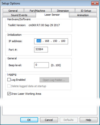
Open the Setup Options dialog (Edit | Preferences | Setup) and click the Laser Sensor tab to show the options for your camera.
Setup Options dialog box - Laser Sensor tab example for the CMS sensor
Hardware/Software Area
This area displays the current CMS toolkit version.
Initialization Area
You can use the IP address and Port # boxes to define the IP address and the port number of the CMS controller.
General Area
You can use the Beep level box to set the volume for beep sounds that come from the CMS controller. It can accept any value from 0 to 100. A value of 0 turns off the volume completely.
Logging Area
Logging area - You can use this area to generate text-based log files that contain communication results between PC-DMIS and the laser sensor when the measurement routine executes. The information it sends to the log files includes scans, nominals of calculated features, and so on. Hexagon Technical Support can use these files to resolve issues that involve your laser sensor.
Log Enabled - This check box enables or disables data sent to the log files.
Open Log Folder - This button opens up the folder that contains your log files.
Typically, PC-DMIS stores these files in the "C:\ProgramData\Hexagon\PC-DMIS\2021.2\NCSensorsLogs\" folder.
Delete logged data at startup - This check box deletes the logged data files from the log folder whenever you create a new measurement routine.
Draw Laser Working Area Check Box
If you select the Draw Laser Working Area check box, CMS probe parameters draw the trapezoid with the correct dimensions. This functionality helps with simulation in Offline mode. This feature is available for laser Auto features and laser scans.
For a laser Auto feature, the trapezoid that represents the working area of the laser is shown in the center of the feature. The trapezoid moves according to the simulation of the laser stripes. For an example, see the images below:
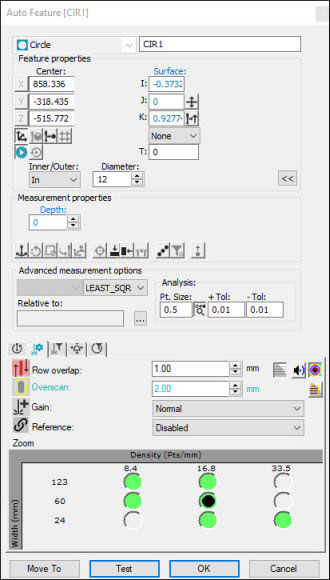
Example of Circle Auto Feature dialog box
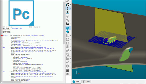
Example of Circle Auto Feature
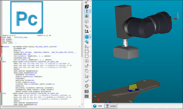
Example of Circle Auto Feature
For a laser scan, the trapezoid that represents the working area of the laser is shown as the start point. The trapezoid moves according to the simulation of the laser stripes. For an example, see the images below:
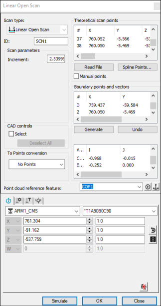
Example of Linear Open Scan dialog box
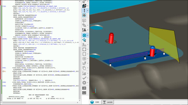
Example of Linear Open Scan
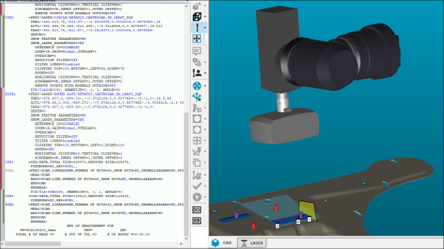
Example of Linear Open Scan
If you change the zoom settings (located on the Laser Scan Properties tab) and sensor-based clipping settings (located on the Laser Clipping Region Properties tab), PC-DMIS updates the trapezoid.
You must have an active Internet connection to see this video.
