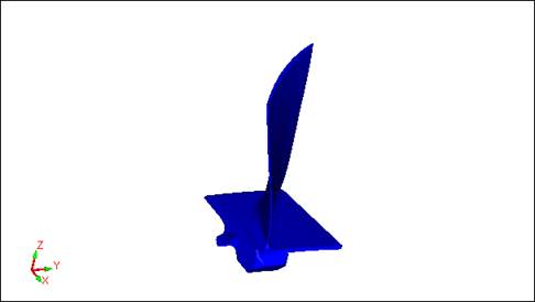
You can use the Blade Scan command to scan blade sections as required by the PC-DMIS Blade Analysis software. The Blade Scan command enables you to measure blade sections in any order of convenience.
The Blade Scan command works with BladeRunner, which is airfoil measurement software that executes your Blade measurement routine in PC-DMIS.

Blade section
Supported Blade Types
The Blade Scan command supports the following types of blades:
Blades with normal nose and tail ends
Blades with a square end at the nose or tail, or square ends at both sides
Blades with partial ends at the nose or tail, or partial ends at both sides
Skew sections
The Blade Scan command does not support Blisk.
Requirements
The Blade Scan command requires the following:
An analog probe. This type of probe can scan continuously without leaving the part.
LSPX1, LSPX3, SP25, and SP600
A nominal file prepared in PC-DMIS Blade Analysis. The Blade Scan command needs to read the nominal file for the blade (BladeName.nom). Refer to the documentation for PC-DMIS Blade Analysis for more information on the nominal file and how to prepare it.
The Blade Scan command works only in DCC mode. Place your measurement routine in DCC mode. For help, refer to the "Probe Mode Toolbar" topic in the "Using Toolbars" chapter in the PC-DMIS Core documentation.
Recommended Blade Position
You can position the blade on the fixture so that:
The LE (leading edge) is toward you or facing the front of the Global CMM.
The line joining the LE and TE (trailing edge) should be approximately parallel to the Y axis of a Global CMM.
The Z axis of the blade is parallel to the Z axis of the CMM.
Probe Tips for Blade Sections
You may need to use different tips for different blade sections. To do this, you need to create two Blade Scan commands with a TIP/ command between them. The first Blade Scan command enables those sections that can be scanned by the first tip. In the second Blade Scan command, enable the sections that can be measured by the second tip.
Additional Information
If you need to scan most of the blade sections in a bidirectional pattern, and only the lower or top section needs to be measured in a unidirectional pattern, create two or more Blade Scan commands, and enable only the sections that each command can measure. You can then set the unidirection or bidirection for each command.
The Blade Scan command creates internal measurement routine features. These features are named in this format:
<Command Name>.ITEM[<Section Name>]
<Command Name> is the Blade Scan Command name, and <Section Name> is the section name.
For example:
BLDSCN1.ITEM[A-A]