To create a Blade Section command, do the following:
Create a measurement routine in PC-DMIS.
Use any scanner device to measure the COP. You can also import a COP. For more information, refer to the PC-DMIS Laser documentation.
Ensure that you have scanned the part all around where the sections are to be cut, and have enough points, especially on the leading and trailing edges.
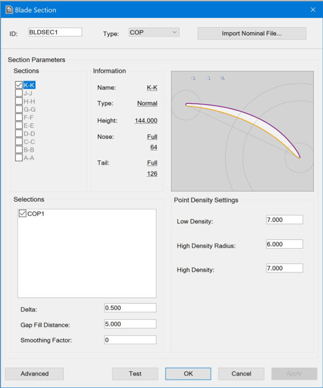
To construct blade sections, select Insert | Modules | Blade Section to open the Blade Section dialog box. Here is an example:

Blade Section dialog box
Complete the items in the dialog box.
Item |
Description |
ID box |
Enter the name of this Blade Section command, or use the default (recommended) ID. |
Type list |
Select COP or Mesh. |
Import Nominal File... button |
Use this button to import the Nominal file for the blade.
PC-DMIS reads the Nominal file and display the information from it in the appropriate parameters in the Section Parameters area. When you import the Nominal file, the Blade Section command refers to the Blade Scan Lookup Table (BladeScan.LookupTable.xml) and inserts the suggested point density for the chord length of the blade. You can then modify these parameters. For more information about the table, see "Modifying the Blade Scan Lookup Table". You can use the Blade Section command to section full sections, partial sections, square sections, and skew sections. |
Sections area |
This area displays all of the blade section names in the Nominal file that you imported. The Blade Section command sections (constructs) only the blade sections that are selected in this area. By default, all of the blade sections are selected for sectioning (constructing). If you do not want to section (construct) a certain blade section, clear its check box. To select a blade section, click its check box. You can set the parameters in the Selections, Low Density Zone, and High Density Zone areas for multiple blade sections at one time by doing the following:
Only the parameters modified in this way are changed. |
Information area |
This area displays the parameters for the blade section that you selected in the Sections area. |
View area |
This area displays the CAD model for the blade section that you selected in the Sections area. (If you selected two or more sections, the View area is blank.) These zoom options are available:
You can also do the following in the View area:
|
Selections area |
This area displays all of the available COPs or Mesh in the measurement routine. Delta box - Applies to the COP type only. This value is the distance within the section height that the Blade Section command looks for points in the COP. Gap Fill Distance box - Applies to the COP type only. This box displays the current setting for the CrossSectionMaximumEmptyLength registry entry in the Settings Editor application. For more information, refer to the documentation for the Settings Editor application. Smoothing Factor - When this value is set to 0 (zero), a very small internal smoothing factor is applied. When you use the Smoothing Factor, PC-DMIS applies a Least Square fit with a smoothing constraint to an ordered set of points. For more information, refer to the "CROSS SECTION" topic in the PC-DMIS Laser documentation. |
Low Density Zone, High Density Zone , and High Density Radius areas |
Low Density Zone - This zone defines the default point density for the blade section. This can be set equal to the point density required in the middle part of the blade. High Density Zone - This zone defines the points near the tail and nose area. The points at a higher density are required to measure the sharp ends accurately. High Density Radius - This zone defines the high density point zone. Enter the radius value with tail or nose points as the center. High density zones display as circles in the View area. |
Test button |
Click this button to perform a test scan of a blade section as follows:
|
Apply button |
Click this button to set all of the parameters for each blade section that you selected in the Sections area. |
When the command is executed, the section that is currently being cut appears in the status bar at the bottom of your screen.
To cancel this Blade Section command and close the Blade Section dialog box, click Cancel.
Use the Blade Report command to create a Report file (.rpt) that the Blade Analysis command can read.