To create a roughness probe file, do the following:
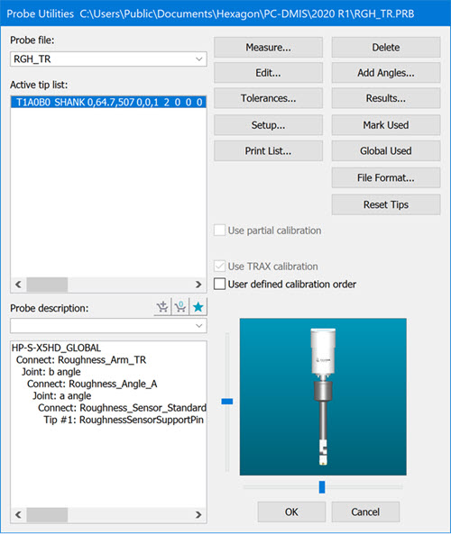
Select the components for the roughness probe in the Probe Utilities dialog box (Insert | Hardware Definition | Probe). The following is an example:

Probe Utilities dialog box
For help with this dialog box, see the "Defining Probes" topic in the "Defining Hardware" chapter in the PC-DMIS Core documentation.
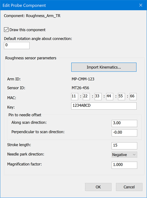
Double-click on the roughness arm component in the Probe description area. (In the example above, you would double-click on Roughness_Arm_TR). The Edit Probe Component dialog box appears:

Edit Probe Component dialog box
Kinematics - This defines the sensor geometry. The sensor is calibrated to determine actual parameters. These parameters are written in .xml file. The calibration is performed at the factory and an xml file is supplied with the sensor.
If you have an .xml file, you can import the parameters and define probe files according to the calibration data.
If you don't have an .xml file, you need to define the minimum parameters in the Edit Probe Component dialog box.
Define the sensor device's parameters through Kinematics file:
Click the Import Kinematics button. This opens the dialog box to select a kinematics file. You need to select a file that is supplied with your sensor.
PC-DMIS reads an .xml file to fill the parameters in the Edit Probe Component dialog box. You need to ensure that the Arm ID and Sensor ID shown in the dialog box matches to the actual sensor mounted on machine.
Click OK to apply parameters and create a probe file that uses kinematics.
If you replace the sensor, you must re-import the kinematics. If you repaired your sensor, you might need re-calibration for kinematics. After you update the kinematics file, you need to import the probe file again.
If you do not have kinematics file, you need to type the following information in the Edit Probe Component dialog box.
MAC - Type the MAC number of your roughness sensor. This number is unique for each sensor. The device certificate that you received with your roughness kit lists the number. Enter it exactly as it appears on the certificate, and double-check your entry.
Key - Type the password for your roughness sensor. The device certificate that you received with your roughness kit lists the password. The password is case-sensitive.
PC-DMIS uses the MAC number and key to connect to your roughness sensor through Bluetooth.
Pin to Needle Offset - This defines the distance of the needle from support pin. You need to define in two directions:
Along scan direction
Perpendicular to scan direction
The distance may be stated on your device certificate. If necessary, you can measure it on any optical machine and enter the value.
Stroke Length - This defines the length your device can scan. The length may be stated on your device certificate. Type that value in this box.
Needle park direction - After you measure roughness, the needle needs to be moved at its park position. The park position depends upon the type of sensor and head. On standard sensor, you can reach the park position with a move in negative direction. On sensor with oblique cone at the end, you can reach the park position with a move in positive direction (Positive direction is the direction of scan.)
Magnification Factor
You can use the roughness standard to determine the amplification factor. To determine the amplification factor, refer to the appropriate geometrical product specification. For help with the magnification factor, see "Determining the Magnification Factor". This information is not recorded in kinematics file. You need to perform this procedure at regular intervals and ensure to enter the correct value.
More: