
You can insert measured features into your measurement routine from the physical part by taking probe hits on that feature.
To insert a measured feature, follow this general procedure:
On the physical part, locate the desired feature.
From the Measured Features toolbar, click the feature type. This tells PC-DMIS that you are about to take hits on a feature of that type. This ensures that the proper feature is created in your measurement routine when you finish taking the necessary number of hits.
Measured Features toolbar
Use your jog box and probe the needed number of hits on the feature.
Then press the DONE button on your jog box or the End key on your keyboard to insert that feature into the Edit window.
You can also use the Quick Start interface to create measured features. For more information on that interface, see "Using the Quick Start Interface" topic in the "Using Other Windows, Editors, and Tools" chapter in the PC-DMIS Core documentation.
If you don't use any of these toolbar buttons, or if
you click the Measured Guess button ( ), PC-DMIS guesses the correct feature type based
on the number of hits and their vectors.
), PC-DMIS guesses the correct feature type based
on the number of hits and their vectors.
As you take hits and once you create the feature, PC-DMIS draws the measured feature on the screen. For 3D-measured features (Torus, Cylinder, Sphere, Cone) and for the 2D Plane feature, PC-DMIS draws the feature with a shaded surface.
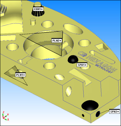
Some sample measured features drawn with shaded surfaces
Hiding Shaded Plane Features
To hide shaded planes, set the None option in the Display area of the Measured Plane dialog box. To globally hide all drawn shaded planes for future plane features, mark the Do Not Display Plane check box in the Setup Options dialog box.
Changing Feature Color
You can use the ID Setup tab in the Setup Options dialog box to modify the feature color used during feature creation. See the Color check box that appears after you choose Features under the Labels For item.
For more information on measured features, see the "Creating Measured Features" chapter in the PC-DMIS Core documentation.
More:
Creating a Measured Round Slot