The Feature Location dialog box (Insert | Dimension | Location) provides you with two methods of entering Plus and / or Minus tolerances for these available axes:
ALL = All the axes and options displayed in the Axes drop down list in the Tolerances area.
X = X axis value
Y = Y axis value
Z = Z axis value
D = Diameter
R = Radius (half the Diameter)
A = Angle (for Cones)
L = Length (used for cylinders, slots, cones and ellipses)
H = Height
PR = Polar Radius
PA = Polar Angle
AR = Area (for Blob features)
T = Error along the approach vector (for points on curved surfaces)
RT = Deviation along the Report vector
S = Deviation along the Surface vector
RS = Deviation along the Surface report
PD = Diameter of a circle (perpendicular to the pin vector)
FORM = Feature's integrated form dimension.
For a circle or cylinder feature, this is the Roundness (RN) dimension.
For a plane feature this is the Flatness (FL) dimension.
For a line feature this is the Straightness (ST) dimension.
1) Old Method - Use the Tolerances Area

The Tolerances area allows you to type plus and minus tolerances for each of the following axes found in the Axes drop-down list.
To enter in plus and minus tolerances:
Select the axis for which you will enter the tolerance from the Axes drop-down list.
In the Plus box type the plus tolerance value for this axis.
In the Minus box type the Minus tolerance value for this axis.
Repeat the above steps for any axes with tolerance values.
2) New Method - Use the Expanding Grid
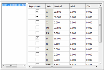
When you select a feature from the main feature list and click the More>> button from the Feature Location dialog box, the dialog box expands vertically to provide you with a grid into which you can more easily specify tolerance and nominal values for desired axes. In addition, an Update Feature Nominal column lets you update the associated feature's nominal values as desired.
The grid appears blank unless you select one or more features from the dialog's main Feature List box.

List of Features - The list to the left of the grid's columns contains any feature or features you selected from the dialog's main Feature List box. Once one or more features appear here, select a feature from the list. PC-DMIS will then display the possible axes for that feature to which you can apply tolerance values.
Report Axis - This column contains check boxes for each axis. A selected check box sends that axis to the report.
Axis - This column lists available axes for the selected feature.
Nominal - This column contains nominal values. You can overwrite them by clicking on them and typing different values.
+Tol / -Tol - The plus and minus tolerance columns provide fields into which you can type tolerances for the various axes used in your dimension.
Update Feature Nominal - This column lets you specify whether or not any changes you made to the nominal values should get applied not only to the dimension but to the feature as well.
Entering Positive-lower and Negative-upper Tolerances
PC-DMIS allows positive-lower tolerances (or a positive tolerance in the negative range). This is done by entering in a minus sign before the value in the Minus box.
PC-DMIS also allows a negative-upper tolerance (or a minus tolerance in the positive range). This is done by entering in a minus sign before the value in the Plus box.
If 1.000 is entered for the nominal, .003 is entered for the plus tolerance and .001 is entered for the minus tolerance it would be interpreted as 1.000 + .003 / –.001. To get the lower tolerance to be +.001 (sign change) simply type in 1.000 (nominal), .003 (plus tol) and –.001 (minus tol) thereby achieving a tolerance range of 1.000 + .003 / + .001.
Negative lower tolerances may be displayed with a minus sign if the Minus Tols Show Negative option has been selected. See "Minus Tols Show Negative" in the "Setting Your Preferences" chapter.