Although there are many different combinations of features that may be used as datums for Position dimensions, there are some general principles to follow when selecting datum features. One common scenario for designs that utilize Position dimensions is to use a circle or cylinder as the sole datum feature.
Another accepted practice is to select a set of datum features that follow 3-2-1 alignment principles. (Remember, the minimum definition for a datum is 3 datum points to describe the first datum, 2 datum points to describe the second datum and 1 datum point to describe the third datum.) This means that the selected features would be a plane, a line, and then a single point.
However, 3-2-1 alignment principles can also be used with plane/line/line, plane/line/circle, plane/cylinder/cylinder, and many other combinations.
When multiple circular features have been used with the Maximum Material Condition (MMC ) or Least Material Condition (LMC ),
The bonus tolerance from the TP axis will not likely be a simple addition of other bonus tolerances, as a best-fit calculation will occur to determine the correct bonus tolerance.
Any circular or slot features may be measured using MMC or LMC.
All non-circular features are measured Regardless of Feature Size (RFS ).
When datum features have been selected, the Position's X,Y,Z, PA, and PR axes are calculated with respect to the alignment of the datums, but are displayed in the current alignment in order to interpret the values. Also, the datum features must be selected using the general steps discussed in this topic or else the dimension is likely to give unexpected results.
General Rules for Position Dimensions when Use Datums is Selected:
Select all the datums specified in the feature control frame so that proper fitting is performed. The features selected for datum 1, datum 2 and datum 3 represent the Primary, Secondary, and Tertiary Datums and are used to constrain up to six degrees of freedom (3 degrees of translation and 3 degrees of rotation).

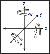
This diagram shows the six degrees of freedom in 3D space (x,y,z,u,v, and w)
Ensure that all Measured Feature commands (datums and feature) contain the correct nominal values (X,Y,Z,I,J,K) in the THEO field. (The fitting process references the measured feature commands to calculate datum constraints and the dimensional results.)
The Measured Feature command and the associated Position Dimension command must come from the same alignment (ensures the nominal values are correct and the same as what is called out as basic dimensions on the drawing). This is critical when programming without CAD as it will require editing measured feature commands (guess mode) to provide the correct nominal values (used for fitting).
DO NOT use Ignore CAD to Part option on the General tab in the Setup Options dialog box (Edit | Preferences | Setup).
We recommend that you use the newer Position Feature Control Frame method of dimensioning when there are modifier(s) (MMC or LMC) on the Datum(s). The Legacy Position command with Use Datums selected is available for measurement routine migration.
Bonus Refinement
When calculating the bonus on a datum, if there is a previous Position dimension or orientation dimension on that datum feature, then the Position and/or orientation tolerance is added to the datum bonus to calculate the virtual size of the datum.
More: