You can use exclusion planes to remove all points within the defined area of the plane. To enable this feature, select the Exclusion Plane check box.
You can click the Collapse
button  to hide sections
of the Laser Data Collection Settings dialog
box or click the Expand button
to hide sections
of the Laser Data Collection Settings dialog
box or click the Expand button  to display hidden sections
of the dialog box.
to display hidden sections
of the dialog box.
When you select the Exclusion Plane
check box, the software activates the Pointcloud Data
Collection Parameters button ( ) for
the defined exclusion plane. If the button on the toolbar is in the active
state, filtering is enabled. Once activated, the software uses the exclusion
plane the next time you execute the measurement routine.
) for
the defined exclusion plane. If the button on the toolbar is in the active
state, filtering is enabled. Once activated, the software uses the exclusion
plane the next time you execute the measurement routine.
You can tell when the exclusion plane is active in your measurement routine by how the Pointcloud Data Collection Parameters button appears on the QuickCloud or Pointcloud toolbar. If the button appears to be pressed in, the exclusion plane is active; otherwise, it is not active.
There are three ways to define the exclusion plane:
1. Measure
Use a contact probe or laser sensor to measure the exclusion plane.
Click the Measure button and then take three hits with a contact probe to measure the exclusion plane. With a laser sensor, scan the area of the plane. If an alignment already exists, the plane is automatically defined in that alignment. If not, the plane is defined using the machine coordinates. If that changes, you need to redefine the plane.
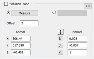
2. Entering the XYZ and IJK values
You can also define the exclusion plane by its normal vector and an anchor point. The exclusion plane is independent of the data filtering.
To define an exclusion plane:
Edit the XYZ anchor positions if necessary.
Click the I, J, or K
normal button that your plane is relative to and edit the value if
necessary. To automatically change the direction of the normal value,
you can click the Reverse Direction button
 .
.
If PC-DMIS is in Online mode, you can click the Measure button to measure your defined exclusion plane.
Click OK to save your settings.
3. Select an existing plane
Select an existing plane (a plane that already exists in the measurement routine) from the Exclusion Plane Feature list. The Anchor and Normal (vector) fields update accordingly.
By selecting an existing plane, when the measurement routine is re-executed and the plane is re-measured, this becomes the new exclusion plane used for the COP. This is useful for portable devices if the device is moved or if the part is moved to a different surface.
Offset - This offsets the plane in the defined Normal direction by the value entered (in measurement routine units).
More: