
Auto High Point button
Use the Auto High Point option to search a user-defined region on the part to locate the highest point in the current workplane. This samples the region for the highest point. It does not search existing points in your measurement routine.
When you execute a High Point feature, PC-DMIS searches for and then returns the highest point within the search region. The result of the search is a single point defined by its X, Y, and Z coordinates and approach vector.

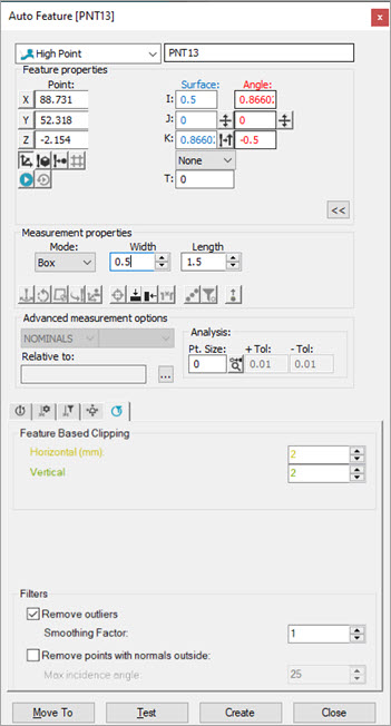
Auto Feature dialog box - High Point
To measure a laser high point with a laser sensor, do the following:
Open the Auto Feature dialog box (Insert | Feature | Auto | Point) and click High Point. You can also access it from the Auto Features or QuickMeasure toolbars (View | Toolbars).
Do one of the following:
Click the CAD in the Graphic Display window to give the point a location and vector. Manually enter any remaining information.
From the Graphic
Display window, use the Laser tab to move
the machine to the point location. Next, from the Feature
Properties area, click the Read Point from
Position button ( ).
Manually enter any remaining information.
Manually enter the theoretical information for X, Y, Z, I, J, K, and so on.
From the Measurement properties area, select either Box or Circular from the Mode list. For details on this area, see the "Measurement Properties Area" section of the PC-DMIS Core documentation.
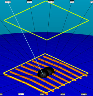
If you select Box from the Mode list, PC-DMIS defines a rectangular search region to determine the high point feature. You can use the Width and Length boxes to define the region.

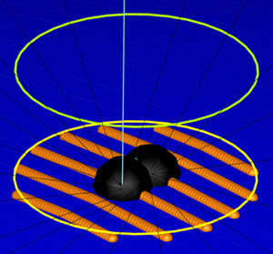
If you select Circular from the Mode list, PC-DMIS defines a circular search region to determine the high point feature.

Click the View Segregated
Points button ( )
from the Laser Scan Properties tab of the
Probe Toolbox to view the segregated points inside the search region
as shown in the above two images.
From the Reference list, select the Pointcloud (COP) or Mesh feature to extract the high point from, or select Disable for direct measurement.
Cycle through the Laser Scan Properties, Laser Filtering Properties, and Laser Clipping Region Properties tabs of the Probe Toolbox and enter all necessary information.
You can click the Test button to test the feature before you create it.
WARNING: When you do this, the machine moves. To avoid injury, stay clear of the machine. To avoid hardware damage, run the machine at a slower speed.
Click Create and then Close.
More: