
Probe Toolbox - Laser AF Multiple Creation tab
The Laser AF Multiple Creation tab is only available for the Laser Edge Point Auto feature. This tab appears when the Pointcloud option on the Laser Scan Properties tab for the Laser Edge Point Auto feature is set to a valid COP ID (the option is not set to Disabled).
You can use this tab for extracted Auto features where the element is extracted from an existing COP object. You cannot use it for features that you directly measure (that is, features where the Pointcloud option is set to Disabled).
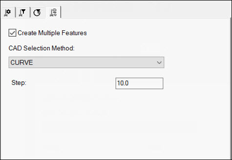
Create Multiple Features - To select curves on the model to create multiple features, select this check box. For Surface Point features, surfaces are selected instead. Note the following:
The curves must be contiguous. To select or deselect them, press Ctrl. Consider these examples:
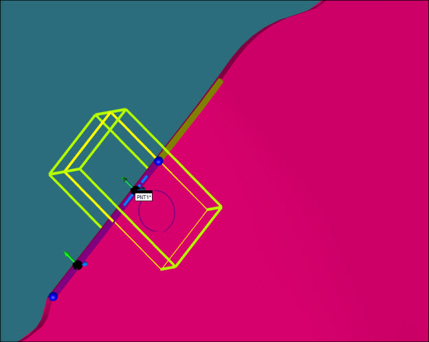
Using Ctrl to select additional contiguous curves
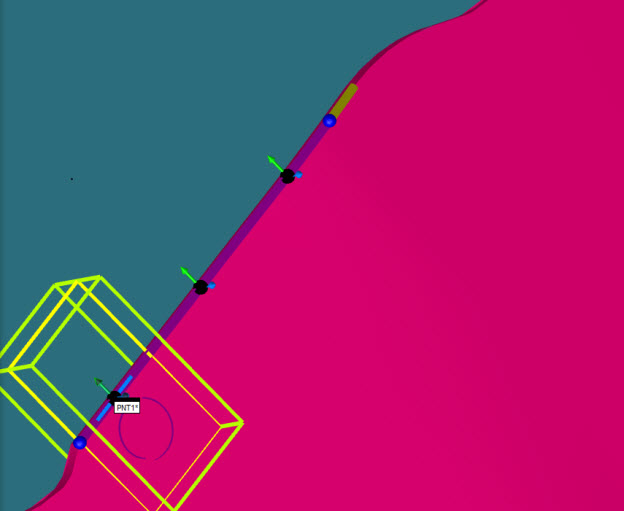
Using Ctrl to select additional contiguous curves
The first point PC-DMIS creates on the curve is at a distance equal to the Horizontal Clipping value plus the Spacer value with respect to the start point of the curve itself. This is done on purpose so that PC-DMIS does not extract the first point off of the desired curve. For example:
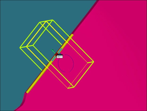
First curve selection
You can use the dragging functionality to select portions of the CAD curves. The features update accordingly.
If you clear the Create Multiple Features check box, the edge point has surface and edge vectors set as a starting point to allow you to tune the extraction parameters. This has no effect on the vectors of the features that you create if the Create Multiple Features check box is selected.
PC-DMIS creates the vectors for those features based on the selection of the surface close to the curve. In other words, the surface vector of the resulting features is the one on the surface (close to the curve) that you need to click to select the curve itself. Therefore, to avoid unpredictable or flipped vectors, we recommend that you do not click exactly on the curve.
CAD Selection Method - Select the desired CAD element.
Step - This option enables you to select the spacing along the selected curve or curves between the features you are creating.
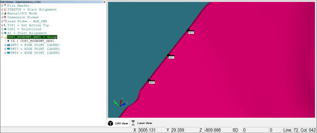
A result of a multiple creation appears below:
