Num Sides - This parameter defines the number of sides used on the polygon. For Laser devices, the number of sides for the Auto feature Polygon is fixed at 6.
Diameter - The value in this box defines the polygon's diameter.
Depth - This parameter controls what data PC-DMIS uses to calculate the feature characteristics. You can use the depth value to eliminate data on a chamfer or some other transitional portion of the feature that you don't want in the feature calculation. Specifying a positive value tells PC-DMIS where along the feature PC-DMIS looks to calculate the feature characteristics. A depth of 0 causes this feature to be calculated at the surface plane height, using data found at the lowest possible depth from the surface plane. A depth of any other value causes it to be calculated at that depth. Due to hardware limitations, for this feature type if you do use a depth value higher than 0, you must use a minimum of 0.3 mm (.01181 inches).
The depth defaults to zero. This is the default value for a plane feature with no extruded edges. You should only change this to a different value if there are specific requirements from your part's drawing. Otherwise, PC-DMIS unsuccessfully attempts to locate points at the specified depth, resulting in a feature calculation error from the feature extraction module.
For example, a depth of 3 indicates that you want to use all data 3 mm (or inches, depending on the units of the measurement routine) and above for the calculation. If you specify 0, this indicates that you want to use all available data for the calculation. For thin walled features, a 0 value may be valid; but for parts with any depth to them, you probably need to specify a depth to get accurate results.
Even if you specify a depth greater than zero, the measured results are always projected into the plane where the feature resides.

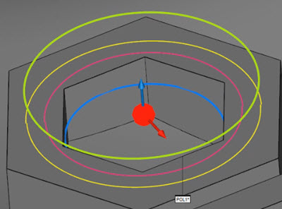
Sample Polygon in the Graphic Display window showing:
the Ring Band (pink circles)
the Horizontal overscan (yellow circle)
the Vertical overscan (green circles)
the Depth (blue)