C Axis lathes have a C Axis control. That is, the macros for these lathes can rotate the spindle and read back the current rotation angle. You can define a C Axis in the NC Server application. For information on how to do this, see the NC Server documentation.
For information on the NC Server operation, please consult the NC Server PDF manual provided with your NC Server application. You can download NC Server from the Universal Updater application.
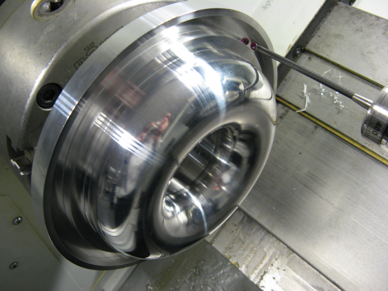
PC-DMIS NC has been adapted by building on dialog boxes found in PC-DMIS Vision to obtain a groove calibration where both the inside and outside diameters are probed. An example of a calibration groove is shown below:
Groove Calibration Example
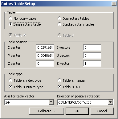
To open the Rotary Table Setup dialog box, select Edit | Preferences | Rotary Table Setup, and ensure that you select the Single rotary table option. If you are calibrating from scratch, clear the offsets as shown below:
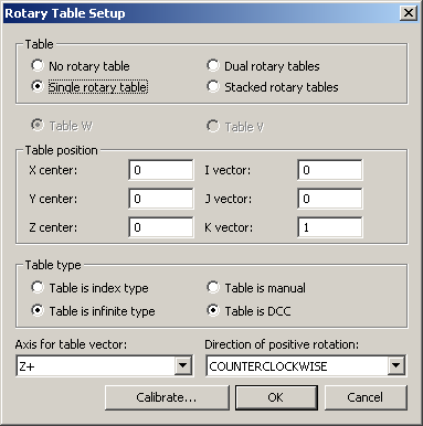
Rotary Table Setup Dialog Box
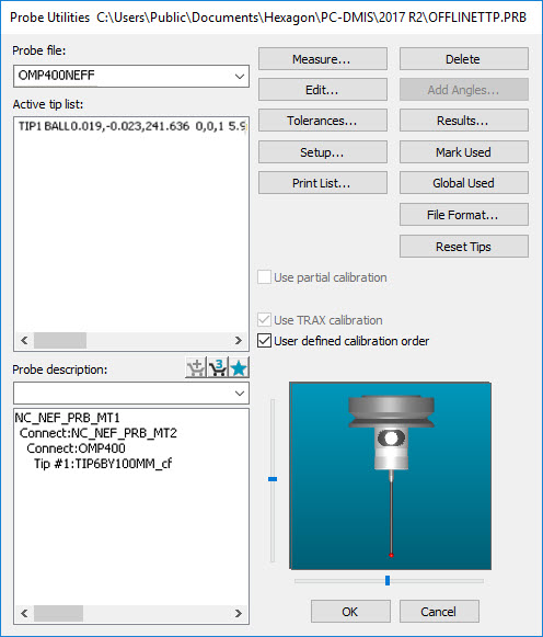
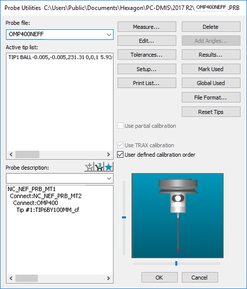
Use the Probe Utilities dialog box to select or create a tip:
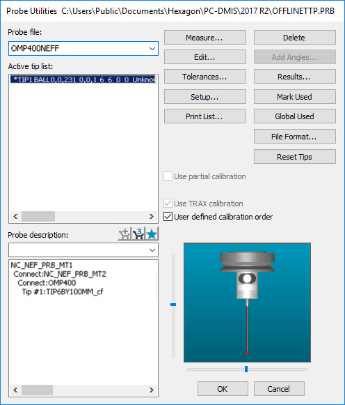
Probe Utilities Dialog Box
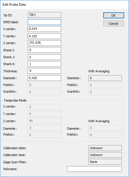
From the Probe Utilities dialog box, click Edit to view or edit the probe data. Click OK to accept any changes and return to the previous dialog box, or click Cancel to return without saving.
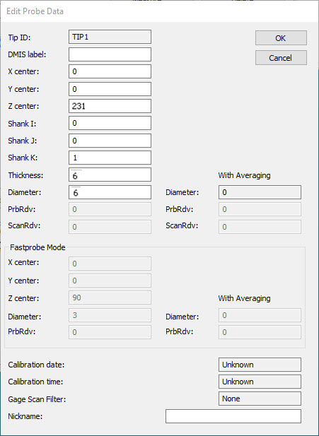
Edit Probe Data Dialog Box
From the Probe Utilities dialog box, click Setup to view, edit, and set the probe setup values as necessary. Click OK to accept any changes and return to the previous dialog box, or click Cancel to return without saving.
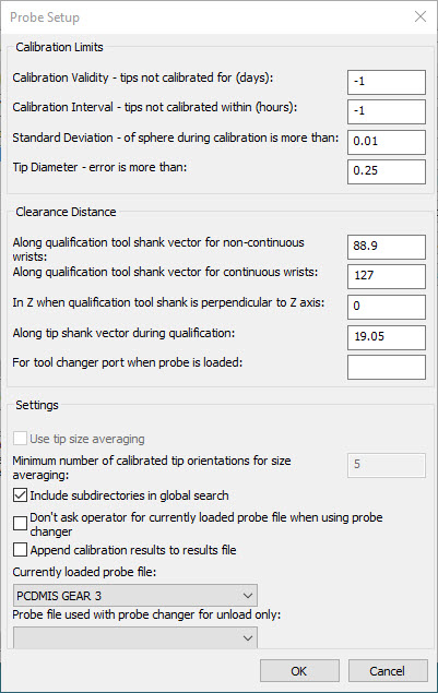
Probe Setup Dialog Box
From the PC-DMIS Probe Utilities dialog box, click Measure, and select a ring tool as shown below:
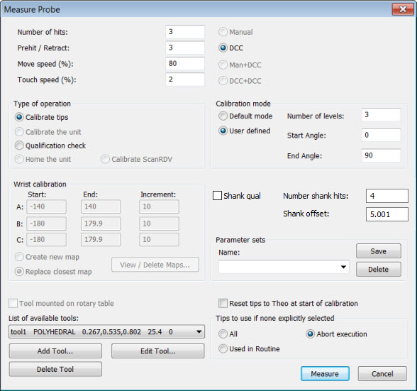
Measure Probe Dialog Box
Click Edit Tool to update the groove parameters or create a new tool setup. The Edit Lathe Tool dialog box appears:
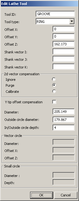
Edit Lathe Tool Dialog Box
From the data in the above image, PC-DMIS measures 4 mm deep into a groove at Z=162.173 mm with an outside circle of diameter 179.867 mm, an inside circle of diameter 205.149 mm, and a plane with an offset equal to the prehit distance beyond the 205.149 circle.
After completion, click OK to return to the Measure Probe dialog box. Then click Measure to create the calibration measurement routine in the Edit window.
Calibration on a ring instead of a groove is done by making the Outside circle diameter larger than the Inside circle diameter.
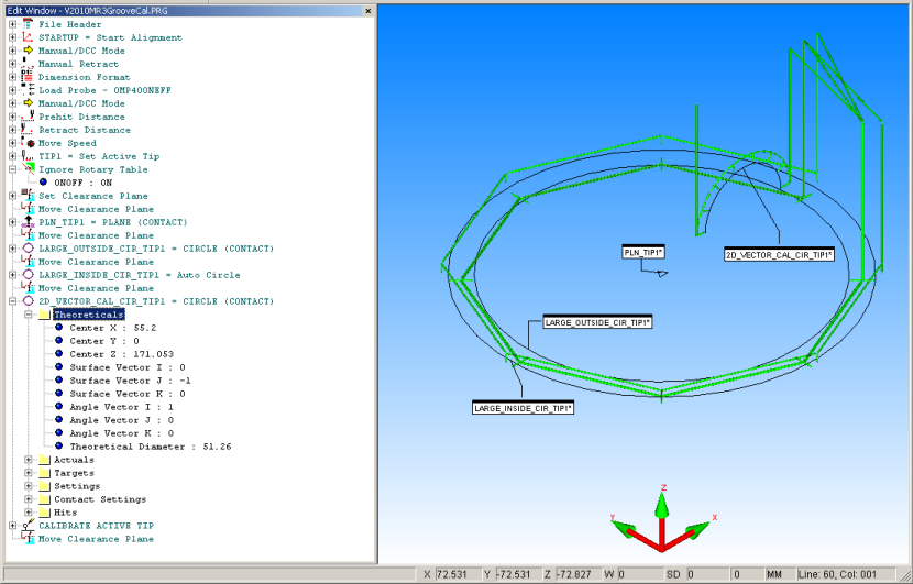
View the path lines, and check the path in the Graphic Display window as shown below:
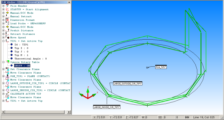
Display of Groove Calibration Path Lines
This calibration ignores any offset due to the probe tip being offset in the Y axis. It is robust in that it allows re-calibration using the current values. In practice, it has given similar results to the following calibration, which adds a further small circle to compensate for the Y offset.
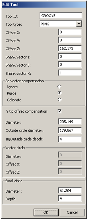
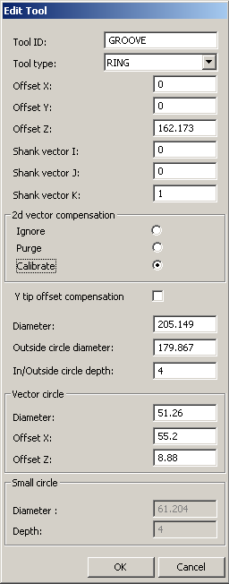
Edit Tool Dialog Box
From the data in the above image, PC-DMIS measures 6 mm deep into a groove at Z=162.173 mm with an outside circle of diameter 179.867 mm, an inside circle of diameter 205.149 mm, a plane with an offset equal to the prehit distance beyond the 205.149 circle, and finally an optional inside circle of diameter 61.204. This latter circle is used if the probe Y offset is required.
After completion, click OK to return to the Measure Probe dialog box. Click Measure to create the calibration measurement routine in the Edit window. View the path lines, and check the path in the Graphic Display window as shown below:
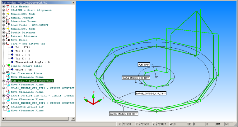
Display of Groove Calibration Dialog Box with Optional Inside Circle
Select Operation | CNC Programming | Create CNC Measurement Routine to create the CNC measurement routine.
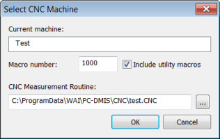
Select CNC Machine Dialog Box
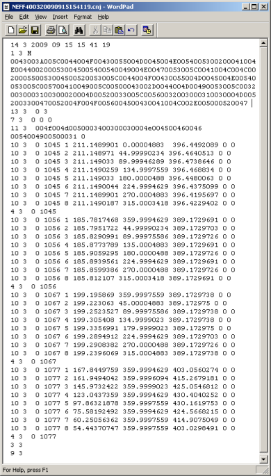
The CNC measurement routine file appears as shown below:
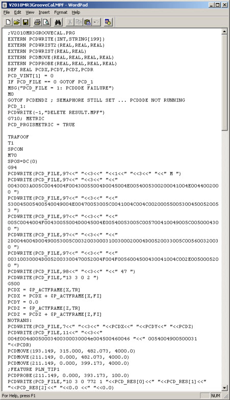
CNC Calibration Measurement Routine Output File
The default is now for non-circular moves inside the groove since circular motion is naturally achieved by the lathe.
Copy the calibration measurement routine to the controller, and run it to produce a journal file as shown below:
This journal file has been adapted from data collected during testing of PC-DMIS Version 4.3 by copying over the file, machine, and feature number identification from the .mpf file generated by PC-DMIS version 2010.
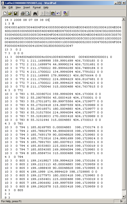
CNC Journal Output File
To verify that the probe calibrations have been updated, open the Probe Utilities dialog box:
Updated Probe Utilities Dialog Box
Click Edit to see the updated details.
For comparison, the first image below is an example of the calibration that uses all three circles:
The image below is an example of the difference seen when using just the two circles.

Comparison of Edit Probe Data Dialog Boxes
The same journal file data has been adapted as before to be used in both cases.
Navigate to the Rotary Table Setup menu option (Edit | Preferences | Rotary Table Setup) to see the updates to the probe tip offset from the rotation center:

Updated Rotary Table Setup Dialog Box
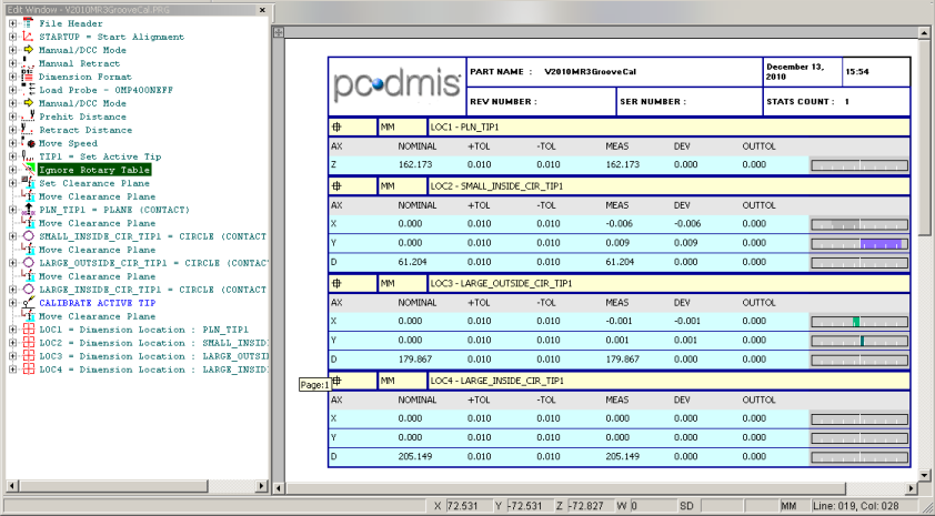
It is instructive to dimension the calibration measurement routine in PC-DMIS to produce a report. Shown below, the deviations come in red. This is because the nominals supplied are so far from true for this calibration artifact.
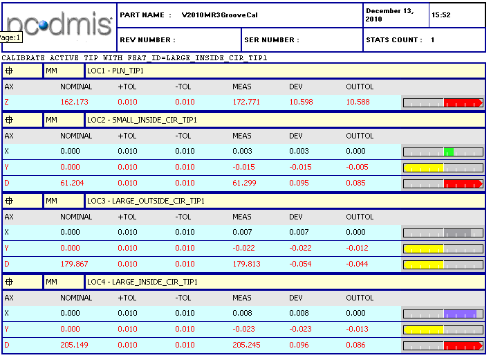
PC-DMIS Calibration Report Dialog Box
To do a sanity check, turn off the Marking the Probe Calibration feature in the measurement routine, turn off the Ignore Rotary Table feature, and re-run the journal file as you would run a normal measurement routine to check if the results are near perfect as shown below:
Updated PC-DMIS Report Dialog Box
In practice, no discernible improvement in measurement accuracy has so far been seen by including the small circle. It creates a Y offset figure in the rotary table settings. Keep in mind the caveat mentioned above, it is recommended that you ignore this option unless absolutely needed.
2D Vector Calibration has been added to the Groove calibration to compensate for out of roundness of the tip ball. Groove calibration only measures at three points on the tip, so this may be insufficient. Vector Calibration measures a number of points around a circular profile.
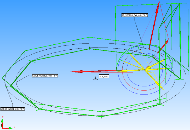
As an example, to use the profile of the torus described above, add the diameter of the circle in the Edit Tool dialog box in the highlighted position as follows, and add the X axis offset of the circle center in the last edit box in the dialog box:
Edit Tool Dialog Box for Vector Calibration
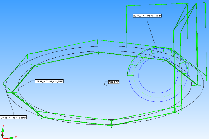
The generated measurement routine is shown below:
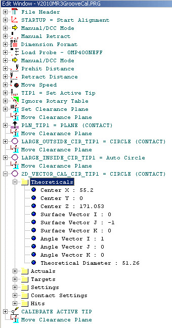
Generated measurement routine for Vector Calibration
This creates a calibration measurement routine as before, but with the addition of a profile measurement. This creates a look-up-table of vector versus tip radius.
Vector Calibration Dialog Box
Select Operation | CNC Programming | Create CNC Measurement Routine to create the CNC measurement routine.
Copy the calibration measurement routine to the controller, and run it to produce a journal file as shown below:
Vector Calibration Journal Output File
Open the Probe Utilities dialog box (Insert| Hardware Definition | Probe) and verify that the probe calibrations have been updated:
Probe Utilities Dialog Box after Vector Calibration
Click Edit to view the new settings after the Vector Calibration is complete:

Edit Probe Data Dialog Box after Vector Calibration
Navigate to the Rotary Table Setup dialog box (Edit | Preferences | Rotary Table Setup) to see the update to the probe tip offset from the rotation center:
Rotary Table Setup Dialog Box after Vector Calibration
If the second vector calibration has been done following the simpler groove or ring calibration, you should see no significant difference to the values in either of the above dialog boxes, because the addition of the second vector calibration option only calibrates the profile of the probe tip.
When you run saved journal files to calibrate and recalibrate with different options selected, make sure the tool dialog box matches too. For example, if you run a simple groove calibration measurement routine (with no second vector calibration) and the corresponding journal file, but the tool dialog box retains the values for the second vector circle, then a bad calibration results. This scenario does not apply when creating fresh calibrations on a machine, because the tool dialog box always matches where a fresh calibration measurement routine is created.
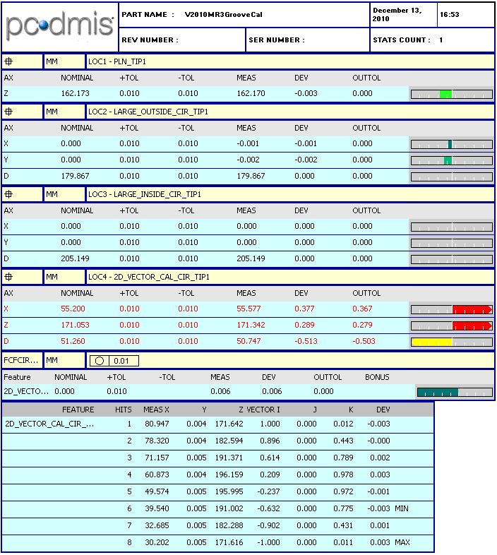
It is instructive to dimension the calibration measurement routine in PC-DMIS to produce a report. In this case, we are also interested in the circularity figure for the profile measurement:
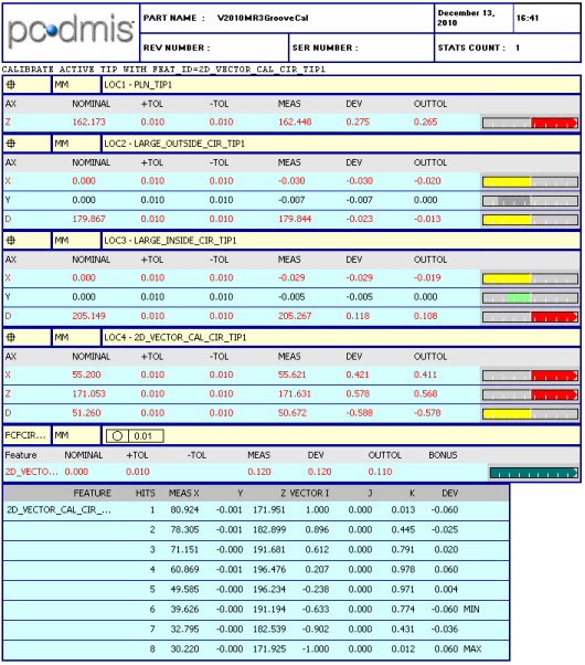
PC-DMIS Report with Dimensioned Calibration Measurement Routine
It is instructive to also include a graphical view of the Circularity, as shown below:
Graphical View of Circularity
As before, to do a sanity check, turn off marking the probe calibration feature in the measurement routine, turn off the Ignore Rotary Table feature, and re-run the journal file as you would run a normal measurement routine to check if the results are near perfect:
Updated PC-DMIS Report after Vector Calibration
As shown below, the Circularity figure is near perfect:
Updated Graphical View after Vector Calibration