An example of a 3D measurement of a test block on a lathe is described below:
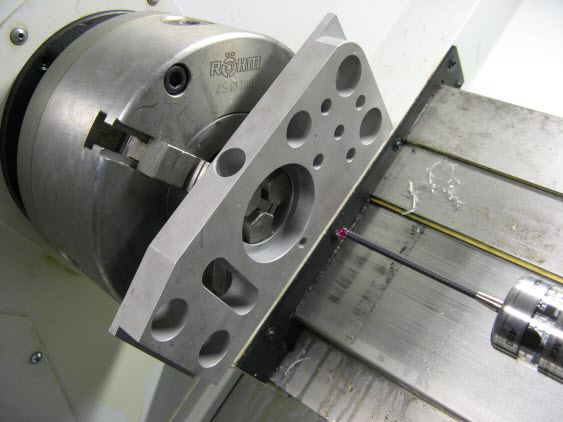
Mount a test block in the lathe chuck via the large center hole in the block.
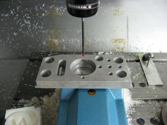
Run a normal PC-DMIS test measurement routine on it as on a CMM or a milling machine using PC-DMIS NC.
Measurement Example on a Fanuc 21i/M Mill
Measurement Example on a Siemens NEF400 Lathe
PC-DMIS NC runs the same measurement routine used on a Fanuc21i/M Mill and gives results on the features on the block to within 10 microns. The Siemens NEF400 Lathe has a OMP400 probe installed while the Fanuc 21i/M Mill has an MP700 probe installed.
In either case, there are very few differences between the two PC-DMIS measurement routine setups with only the selection of the Lathe required. The probe, CAD transform, and alignment of the part in the measurement routine remain unchanged.
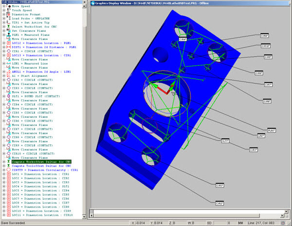
Test Block Measurement Routine
To access points on the left-hand side of the block (X<0), the rectangular to polar conversion results in the block being spun around are required to ensure that the point lies on the X axis (where X>0). A further modification to the Siemens macro computes the spindle speed such that the spindle move takes the same time as the XZ axis move. This results in something that looks like an XYZ axis interpolated move despite the lathe have no Y or C axes.
It should be noted, however, that on a proper XYZ axis machine (such as the Fanuc mill), the 3D moves will be vectoring in on points on a straight line instead of an arc. However, for measurement moves with a small prehit, the error is usually insignificant. The arcing of straight path lines will also mean collision detection cannot always be relied on. Of course, for measurement moves where no spindle motion is required, there is no such measurement error, but to achieve this in the above part, there would need to be some modifications to the measurement routine copied from the milling machine.
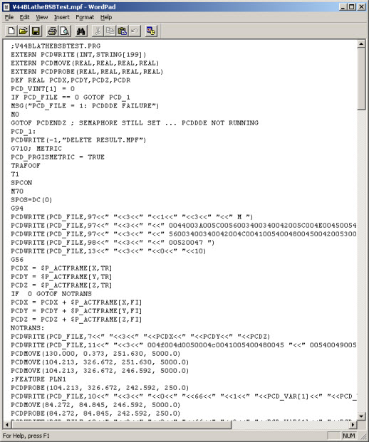
The measurement routine that PC-DMIS generates is only slightly different to a normal 3D measurement that uses a Siemens 840D machine.
PC-DMIS Measurement Routine
Here are the results PC-DMIS returned in the PCD_VAR[] variables, but v2010 and later versions avoid using these user variables. Instead, it returns the results in the new UGUD variables PCD_RES[].
Comparing the Siemens NEF400 Lathe measurement results, with a CMM measuring the same part in the same way, shows reasonable agreement:
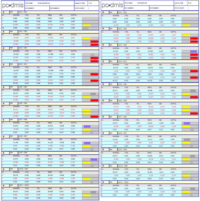
Single Circle Measurement Comparison - Siemens Lathe results on the left, CMM results on the right
The above results were obtained after using Update Work Offset to correct the rotational alignment of the part.
By comparison, using two circles for calibration compares quite well and shows very little difference:
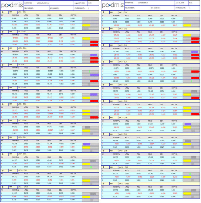
Two Circle Measurement Comparison - Siemens Lathe results on the left, CMM results on the right
The journal file is shown below.
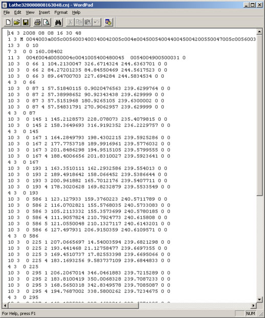
Measurement Journal File