
Portable QuickCloud toolbar
The QuickCloud toolbar is only available if you configure your PC-DMIS license as a Portable device. It provides the buttons to complete all the steps from start to finish for working with Pointclouds.
The toolbar provides drop-down button functionality for the Cross Section, Pointcloud Colormap, Auto Feature, and Dimension buttons. PC-DMIS stores the last-selected option for each button and displays it the next time the QuickCloud toolbar appears.
You can add drop-down buttons to any customizable toolbar in PC-DMIS from the View | Toolbars | Customize menu option.
For details on all Pointcloud toolbar buttons, see "Pointcloud Toolbar" in the PC-DMIS Laser documentation.
The QuickCloud toolbar provides these options:
 Import from CAD file - This button displays
an Open dialog box to import any one of the
supported part models from your library. Select the Files
of Type drop-down list to view the available file types. For details,
see "Importing
a CAD File" in the "Using
Advanced File Options" chapter in the PC-DMIS Core documentation.
Import from CAD file - This button displays
an Open dialog box to import any one of the
supported part models from your library. Select the Files
of Type drop-down list to view the available file types. For details,
see "Importing
a CAD File" in the "Using
Advanced File Options" chapter in the PC-DMIS Core documentation.
 CAD Vectors - This button displays the CAD Vectors dialog box to view and manipulate
surface vectors. For details, see "Editing
CAD Vectors" in the "Editing
the CAD Display" chapter in the PC-DMIS Core documentation.
CAD Vectors - This button displays the CAD Vectors dialog box to view and manipulate
surface vectors. For details, see "Editing
CAD Vectors" in the "Editing
the CAD Display" chapter in the PC-DMIS Core documentation.
 Portable Scanning Widget - This button displays
the Portable Scanning Widget toolbar. When you
connect to a portable device, and the active probe is a laser scanner,
PC-DMIS automatically shows the Portable Scanning Widget
toolbar. For details on the Portable Scanning
Widget toolbar, see "Portable
Scanning Widget Toolbar" in this documentation.
Portable Scanning Widget - This button displays
the Portable Scanning Widget toolbar. When you
connect to a portable device, and the active probe is a laser scanner,
PC-DMIS automatically shows the Portable Scanning Widget
toolbar. For details on the Portable Scanning
Widget toolbar, see "Portable
Scanning Widget Toolbar" in this documentation.
 Pointcloud Filtering Plane - This button displays
the Laser Data Collection Settings dialog box.
You can use it to define scan profiles, data filtering, and an exclusion
plane for your pointcloud data. For details, see "Laser
Data Collection Settings" in the PC-DMIS Laser documentation.
Pointcloud Filtering Plane - This button displays
the Laser Data Collection Settings dialog box.
You can use it to define scan profiles, data filtering, and an exclusion
plane for your pointcloud data. For details, see "Laser
Data Collection Settings" in the PC-DMIS Laser documentation.
 Select Pointcloud - This button provides, by
default, the Polygon selection method. Select the vertices of the polygon
and then press the End key to close it.
Select Pointcloud - This button provides, by
default, the Polygon selection method. Select the vertices of the polygon
and then press the End key to close it.
The Select Pointcloud option differs from the use of the pointcloud operator because the software only applies the function and does not add it as a command. To create the command, open the pointcloud operator and choose the Select method.
 Pointcloud Operator - This button displays the
Pointcloud Operator dialog box. You can use
it to perform different operations on Pointcloud (COP) commands and other
Pointcloud operator commands. For details, see "Pointcloud
Operators" in the PC-DMIS Laser documentation.
Pointcloud Operator - This button displays the
Pointcloud Operator dialog box. You can use
it to perform different operations on Pointcloud (COP) commands and other
Pointcloud operator commands. For details, see "Pointcloud
Operators" in the PC-DMIS Laser documentation.
 Pointcloud Alignment - This button allows you
to create Pointcloud (COP) to CAD and COP to COP alignments. For details,
see "Pointcloud/CAD
Alignment Dialog Box Description" in the "Pointcloud Alignments"
chapter in the PC-DMIS Laser documentation.
Pointcloud Alignment - This button allows you
to create Pointcloud (COP) to CAD and COP to COP alignments. For details,
see "Pointcloud/CAD
Alignment Dialog Box Description" in the "Pointcloud Alignments"
chapter in the PC-DMIS Laser documentation.
 Clean Pointcloud - When you click this button,
the CLEAN operation immediately eliminates outlier COP points. The outlier
points are based on the default Max distance
of the points to the CAD. If the distance of a point is greater than the
value of Max distance, the software considers
the point an outlier that does not belong to the part. To use this operation,
you must have established at least a rough alignment. For details on how
to create rough alignments, see "Creating
a Pointcloud/CAD Alignment" in the PC-DMIS Laser documentation.
For more details on the Clean Pointcloud operator, see "CLEAN"
in the "Pointcloud Operators"
chapter in the PC-MIS Laser documentation.
Clean Pointcloud - When you click this button,
the CLEAN operation immediately eliminates outlier COP points. The outlier
points are based on the default Max distance
of the points to the CAD. If the distance of a point is greater than the
value of Max distance, the software considers
the point an outlier that does not belong to the part. To use this operation,
you must have established at least a rough alignment. For details on how
to create rough alignments, see "Creating
a Pointcloud/CAD Alignment" in the PC-DMIS Laser documentation.
For more details on the Clean Pointcloud operator, see "CLEAN"
in the "Pointcloud Operators"
chapter in the PC-MIS Laser documentation.
 Cross Section - This button opens the Pointcloud Operator dialog box with the CROSS
SECTION option selected in the Operator list.
For details on how to create cross section features, see "CROSS SECTION" in the "Pointcloud Operators"
chapter in the PC-DMIS Laser documentation.
Cross Section - This button opens the Pointcloud Operator dialog box with the CROSS
SECTION option selected in the Operator list.
For details on how to create cross section features, see "CROSS SECTION" in the "Pointcloud Operators"
chapter in the PC-DMIS Laser documentation.
Click the drop-down arrow to display the Cross Section toolbar:
For details on this toolbar, see "Show and Hide Cross Section Polylines" in the PC-DMIS Laser documentation.
 Pointcloud Mesh - This button displays the Mesh Command dialog box. You can use this dialog
box to define a Mesh command from pointclouds. For details, see "Creating
a Mesh Feature" in the PC-DMIS Laser documentation.
Pointcloud Mesh - This button displays the Mesh Command dialog box. You can use this dialog
box to define a Mesh command from pointclouds. For details, see "Creating
a Mesh Feature" in the PC-DMIS Laser documentation.
 Pointcloud Colormap - This button displays the
dialog box for the operator shown on the button.
Pointcloud Colormap - This button displays the
dialog box for the operator shown on the button.
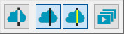
Click the drop-down arrow to display the Pointcloud Colormap toolbar:
The Pointcloud Colormap toolbar allows you to select between the Surface Colormap, Point Colormap, and Thickness Colormap options.
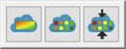
From left to right, the buttons are:
 Surface Colormap - This button displays the Pointcloud Operator dialog box with the Surface
Colormap operator selected. The SURFACE COLORMAP operation applies a colored
shading to the CAD model. PC-DMIS shades the model according to the deviations
of the pointcloud compared to the CAD. The Pointcloud Surface Colormap
operator uses the colors defined in the Edit Dimension
Color dialog box, and the tolerance limits specified in the Upper tolerance and Lower tolerance
boxes. For details on the Pointcloud Surface Colormap operator, see "SURFACE COLORMAP" in
the PC-DMIS Laser documentation.
Surface Colormap - This button displays the Pointcloud Operator dialog box with the Surface
Colormap operator selected. The SURFACE COLORMAP operation applies a colored
shading to the CAD model. PC-DMIS shades the model according to the deviations
of the pointcloud compared to the CAD. The Pointcloud Surface Colormap
operator uses the colors defined in the Edit Dimension
Color dialog box, and the tolerance limits specified in the Upper tolerance and Lower tolerance
boxes. For details on the Pointcloud Surface Colormap operator, see "SURFACE COLORMAP" in
the PC-DMIS Laser documentation.
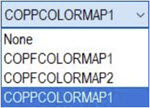
You can create multiple surface colormaps in a PC-DMIS measurement routine. However, only one is active. The last applied and created surface colormap, or the last one executed, is always the currently active colormap.
You can also select which colormap is the active one from the Colormaps list box. When you activate a new colormap, PC-DMIS displays its associated scale with tolerance values and any annotations in the Graphic Display window. To select a new color map, click the Colormaps list box and select the colormap from the list of defined Surface or Point Colormap operators:
 Point Colormap - This button displays the Pointcloud Operator dialog box with the Point
Colormap operator selected. The Point Colormap operation evaluates the
deviations of the data points contained in a COP command compared to a
CAD object. For details on the Pointcloud Point Colormap operator, see
"POINT COLORMAP" in
the PC-DMIS Laser documentation.
Point Colormap - This button displays the Pointcloud Operator dialog box with the Point
Colormap operator selected. The Point Colormap operation evaluates the
deviations of the data points contained in a COP command compared to a
CAD object. For details on the Pointcloud Point Colormap operator, see
"POINT COLORMAP" in
the PC-DMIS Laser documentation.
 Thickness Colormap - This button displays the
Pointcloud Operator dialog box with the Thickness
Colormap operator selected. The Thickness Colormap allows you to show
and measure the part thickness as a colormap from only the Mesh or Pointcloud
(COP) data object. You can also compare the measured thickness to the
nominal CAD model thickness. For details on the Thickness
Colormap option, see "Thickness
Colormap" in this documentation.
Thickness Colormap - This button displays the
Pointcloud Operator dialog box with the Thickness
Colormap operator selected. The Thickness Colormap allows you to show
and measure the part thickness as a colormap from only the Mesh or Pointcloud
(COP) data object. You can also compare the measured thickness to the
nominal CAD model thickness. For details on the Thickness
Colormap option, see "Thickness
Colormap" in this documentation.
 Caliper button - The Caliper
is a quick-check tool that works similarly to a physical caliper. It provides
a local two-point size check on the Pointcloud (COP), Mesh, or COPOPER
(such as the COPSELECT, COPCLEAN, or COPFILTER) object. The Caliper shows
the measured length along the selected axis or direction. For details
on this gage, see the "Caliper
Overview" section in the PC-DMIS Laser documentation.
Caliper button - The Caliper
is a quick-check tool that works similarly to a physical caliper. It provides
a local two-point size check on the Pointcloud (COP), Mesh, or COPOPER
(such as the COPSELECT, COPCLEAN, or COPFILTER) object. The Caliper shows
the measured length along the selected axis or direction. For details
on this gage, see the "Caliper
Overview" section in the PC-DMIS Laser documentation.
 Auto Feature button and drop-down arrow - This
button displays the Auto Feature dialog box
for the icon shown on the button. From the dialog box, you can select
any of the available feature commands to insert into the measurement routine.
Auto Feature button and drop-down arrow - This
button displays the Auto Feature dialog box
for the icon shown on the button. From the dialog box, you can select
any of the available feature commands to insert into the measurement routine.
To display the Auto Feature toolbar, click the drop-down arrow:

For information on Auto Features, see "Inserting Auto Features" in the "Creating Auto Features" chapter in the PC-DMIS Core documentation.
 Dimension button and drop-down arrow - This
button displays the Dimension dialog box for
the icon shown on the button. From the dialog box, you can select any
of the available dimension commands to insert into the measurement routine.
Dimension button and drop-down arrow - This
button displays the Dimension dialog box for
the icon shown on the button. From the dialog box, you can select any
of the available dimension commands to insert into the measurement routine.
To display the Dimension toolbar, click the drop-down arrow:

For information on dimensions, see "Using Legacy Dimensions" and "Using Geometric Tolerances" chapters in the PC-DMIS Core documentation.
 Edit Custom Report from other Measurement Routine
- This button creates a Custom Report from another measurement routine
in your current measurement routine. For details, see "Creating Custom
Reports" in the "Reporting
Measurement Results" chapter in the PC-DMIS Core documentation.
Edit Custom Report from other Measurement Routine
- This button creates a Custom Report from another measurement routine
in your current measurement routine. For details, see "Creating Custom
Reports" in the "Reporting
Measurement Results" chapter in the PC-DMIS Core documentation.
 Insert Custom Report - This button inserts a
custom report into your measurement routine as with the Insert
| Report Command | Custom Report menu function. For details, see
"Embedding
Reports or Templates into a Measurement Routine" in the "Inserting
Report Commands" chapter in the PC-DMIS Core documentation.
Insert Custom Report - This button inserts a
custom report into your measurement routine as with the Insert
| Report Command | Custom Report menu function. For details, see
"Embedding
Reports or Templates into a Measurement Routine" in the "Inserting
Report Commands" chapter in the PC-DMIS Core documentation.