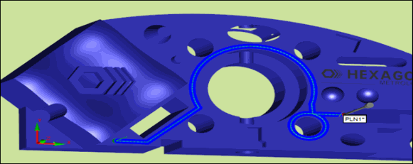
This example of the teach path method for the TTP Free Form Plane strategy shows a detailed procedure for scanning the top surface along a specific path.
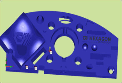
In this example, suppose that you want to scan the top surface along the path shown below:

Scan path
To generate this path, take the hits to define the points as described below. The points are recorded in the list of point on the Path Definition tab. They are marked on the CAD as shown in the procedure.
The first segment in the path is linear. To generate this line:
Select the  button.
Because this is the first segment, take two hits to define points 1 and 2 for the line.
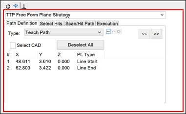
Points 1 and 2 in first segment
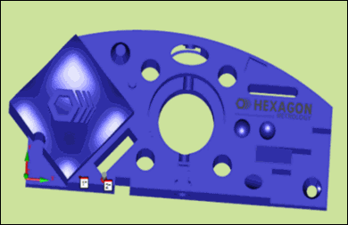
Points 1 and 2 marked on CAD
The second segment in the path is also linear. Point 2 (the last point of the first segment line) becomes the start point of the second segment line. To generate this line:
Keep the  button selected.
Take one hit to define point 3, the end point of the line for the second segment.
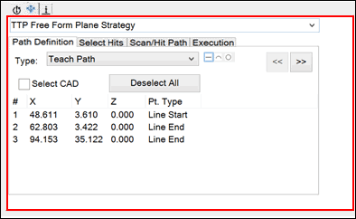
Point 3 in second segment
Point 3 marked on CAD
The third segment in the scan path is an arc along the big circle. Point 3 (the last point of the second segment line) becomes the start point of the arc. The last point is the end point of the arc. To generate this arc:
Select the  button.
Take two more hits on the arc to define points 4 and 5.
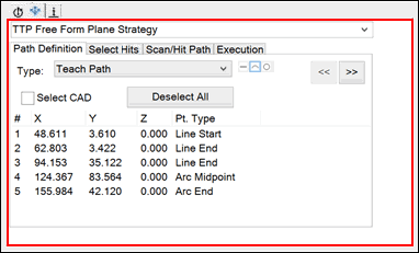
Points 4 and 5 in third segment
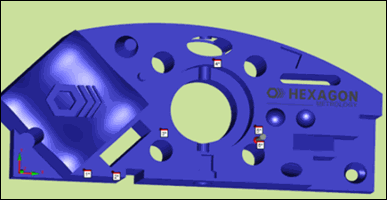
Points 4 and 5 marked on CAD
The fourth segment is a line. The end point of the arc becomes the start point of the line. To generate this line:
Select the  button.
Take one hit to define point 6, the end point of the line for the fourth segment.
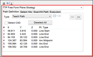
Point 6 in fourth segment
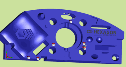
Point 6 marked on CAD
You now need to scan 360 degrees around the small circle. The end point of the line of the fourth segment becomes the start point of the circle. To generate this circle:
Select the  button.
Take two more hits to define points 7 and 8 for the circular path. Because a circle is 360 degrees, point 9 - the end point of the circle - is automatically recorded the same as the start point of the circle.
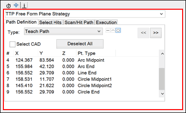
Points 7 through 9 in circle
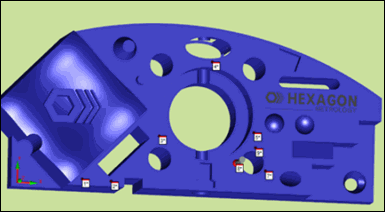
Points 7 through 9 marked on CAD
The last segment is a line. Point 9, the end point of the circle, becomes the start point of the line. To generate this line:
Select the  button.
Take the last hit to define point 10, which completes the scan path.
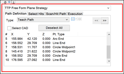
Point 10 in last segment
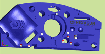
Point 10 marked on CAD
Select the >> button. In the Teach Controls area, in the Increment box, type 1.
Click Generate. The generated scan path appears in the Graphic Display window.
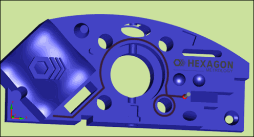
Generated scan path