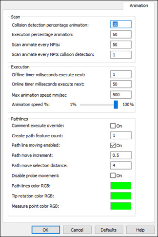
Setup Options dialog box-Animation tab
The Animation tab (Edit | Preferences | Setup) contains offline animation and path line settings.
Collision detection percentage animation: - This defines the percentage of probe animation that occurs during a collision detection operation.
A value of 100 indicates that the display is redrawn at its maximum rate.
A value of 0 indicates that the display is not redrawn at all.
The default value is 50.
Execution percentage animation: - This defines the percentage of probe animation that occurs during normal measurement routine execution.
A value of 100 indicates that the display is redrawn at its maximum rate.
A value of 0 indicates that the display is not redrawn at all.
The default value is 50.
Scan animate every NPts: - This limits the number of points that are used for the animation. For example, if you set this value to 10, PC-DMIS will only take every 10th point, plus the first and last points. This value is used for probe animation during execution. The default value is 50.
Scan animate every NPts collision detection: - This limits the number of points that are used for the collision detection animation. For example, if you set this value to 10, PC-DMIS will only take every 10th point, plus the first and last points. This value is used for probe animation during collision detection.
Offline timer milliseconds execute next: - This sets the frequency of how often PC-DMIS processes commands during execution in Offline mode. This is a number of milliseconds. The default is 50.
Online timer milliseconds execute next: - This sets the frequency of how often PC-DMIS processes commands during online execution. This is a number of milliseconds. The default is 50.
For example if these are set to 1 then PC-DMIS would try to process a command during execution every millisecond.
Max animation speed (mm/sec): - This lets you define the maximum animation speed that the animated probe will use in the Graphic Display window during measurement routine execution. The speed is in mm per second. You may find it useful to alter this value for complex measurement routines that cause the animation to render too slowly. To increase the duration between redrawn views of the animation, increase this value. This will cause fewer animation steps to be drawn.
Animation speed %: - The slider allows you to quickly and easily adjust the actual percentage used of the Max animation speed value.
Changing Animation Speeds: If you want to further fine-tune your offline animation speeds, see the "Executing and Debugging Measurement Routines Offline" topic in the "Working in Offline Mode" chapter.
Comment execute override: - This check box determines whether or not COMMENT commands are executed when you generate path lines. If you mark this check box then they are executed. This check box is cleared by default.
Create path feature count: - This box is used when you select View | Path Lines from Cursor. It defines how many features above and below the cursor location are used. For example, if you set this to 3, PC-DMIS would use three features above and three features below the cursor location. The default value is 1, which means that PC-DMIS draws path lines for one feature that precedes the current feature and one feature that follows the current feature. See "Showing, Animating, and Moving Path Lines" in the "Editing the CAD Display" chapter.
Path lines color RGB: - This box defines the color for generated path lines in the Graphic Display window. Clicking on the color opens up the standard Color dialog box, from which you can choose a new color.
Path line moving enabled: - This check box determines whether or not path-line moving is enabled. If marked, you can click on a path line to insert a MOVE/POINT command at that location. See "Moving Path Lines" in the "Editing the CAD Display" chapter.
Path move increment - This defines the increment distance for moving path lines in the Move Path Line dialog box. See "Moving Path Lines" in the "Editing the CAD Display" chapter.
Path move selection distance - This determines the selection distance from a start and end point of a path line. If the Path line moving enabled check box is marked, and you click on a path line within the specified distance inside the Graphic Display window, PC-DMIS searches for an existing MOVE/POINT command to modify instead of inserting a new MOVE/POINT command that splits the selected path line.
Disable probe movement - This check box is cleared by default, which causes the probe to move during path line creation. If this box is checked, the probe no longer moves during path line creation.
Path lines color RGB - This defines the main path line color as a probe moves between features.
Tip rotation color RGB - This defines the color for a probe's path lines as it rotates its tip to a new angle.
Measure point color RGB - This defines the color for a probe's path lines as it contacts with the part to measure points that define the feature.