
The Theoretical Path area on the Path Definition tab in the scan dialog box (Insert | Scan) contains some or all of these items depending on the type of scan selected:
Theoretical
Path list
This list displays the theoretical pathway that your scan will take when
executed. It displays the XYZ and IJK data for each point. To import points
from a text file, click the Read File button
(if using a Freeform scan). You can also click the Generate
button to have PC-DMIS automatically generate the theoretical points.
In the case of a Freeform scan, you can create these points by clicking
them on the CAD model.
To edit the value of any theoretical point:
Double-click the appropriate point number in the # column. The Edit Theo Data dialog box appears.
Change the values in the desired X, Y, Z and I, J, K boxes.
Click OK. The change appears in the Theoretical Path list.
To cycle through the points in the Theoretical Path list, click the Next button in the Edit Theo Data dialog box. This enables you to edit them one by one.
To delete any theoretical points:
To delete all of the points in the list, right-click on the list and select Delete All Theoretical Points.
To delete a single point, select the point and then click Delete.
Generate
button
First, select the required boundary point. The Generate
button takes information from the CAD model and automatically generates
the theoretical pathway within the scan's boundary for these supported
scans: Linear Open, Linear Closed, Patch, and Section.
PC-DMIS always uses the Find Nominal Tolerance value on the Execution tab when it generates nominal data for the scans and finds the nominals for the learned scan.
Clear
button
Use this button to remove all of the points in the Theoretical
Path list.
Read
File button
This button appears when you use a Freeform scan. It lets you import points
from a text file with a .txt filename extension. The text file should
be in a comma-delimited format with one point on each line, like this:
X,Y,Z,I,J,K
Jump
holes check box
The Jump holes check box determines whether or
not the theoretical path should jump over holes and other hole-like features
in the surface.
If you select the check box, point data that does not lie within the selected surface (such as hole features) does not appear in the Theoretical Path list and will be skipped during scan execution.
If you clear the check box, the routine scans into hole-like features.
When you work with Surface mode and a tactile probe, the Jump holes check box is always selected when the scan spans through multiple surfaces. When you work with Curve mode and a tactile probe, the Jump holes check box is not available for selection. The scan will always jump when multiple curves are selected.
When you work with a spot laser probe in Surface mode or Curve mode, PC-DMIS records the last setting of the Jump holes check box and sets it accordingly.
This appears on all scans but Perimeter and Freeform. It is not supported in these scans.
Edge
offset box
The Edge offset option defines the minimum distance
away from a boundary/edge where scan points are considered valid. Scan
points that are closer to the boundary that the specified offset distance
are not allowed. For example, if you set your offset distance to .5 mm,
any scan point located within .5 mm of the boundary/edge is not allowed.
This is used with the Jump holes option.
PC-DMIS records the value that you enter for the Edge offset option and converts it into the appropriate unit of the next measurement routine.
Get Nominals
button
This button lets you find the nominal after a scan has been learned or
executed. PC-DMIS finds the nominals for the scan from the CAD data that
is available.
To Points
button
This button runs a process where the individual points that make up an
existing scan can be converted into single points after execution. PC-DMIS
creates single points and places them in a group. The Group ID is the
same as the scan ID.
For example:
Place your cursor on a scan using hit data in the Edit window.
Press the F9 key to display the Scan dialog box.
Select the To Points button.
PC-DMIS converts all hit data into single points and creates a group in the Edit window.
Flip
button
This button flips the approach vectors of the theoretical scan point that
is selected in the Theoretical Path list.
Flip
All
This button reverses all of the vectors for all points in the Theoretical
Path list.
Label
Hits check box
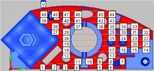
This check box determines whether or not PC-DMIS should label each hit
in the scan. Labeled hits look something like this:

A UV scan with labeled hits