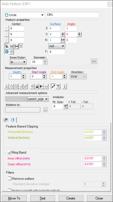
Auto Feature dialog box - Circle
To create a laser auto circle:
Access the Auto Feature dialog box, and select Circle.
Do one of the following:
Perform clicks on the CAD to give the circle a location and vector. Manually enter any remaining information.
From the Graphic
Display window, use the Laser tab to move
the machine to the circle location. Next, from the Feature
Properties area, click Read Point from Machine
 . Manually enter
any remaining information such as the diameter, depth, and other parameters.
. Manually enter
any remaining information such as the diameter, depth, and other parameters.
Manually enter all of the theoretical information for X, Y, Z, I, J, K, diameter, depth, and other parameters.
Enter the necessary information on the Probe Toolbox tabs. Cycle through the Laser Scan Properties, Laser Filtering Properties, and Laser Clipping Region Properties tabs to enter the information.
If desired, click the Test button to test the feature.
WARNING: When you do this, the machine moves. To avoid injury, stay clear of the machine. To avoid hardware damage, run the machine at a slower speed.
Click the Create button and then click Close.
Currently, you can only measure inner circles (holes) with laser sensors.
More: