 ).
).PC-DMIS Laser displays a colored scan-line indicator in the Graphic Display window to represent the location of the actual beam's scan line in 3D space. The indicator only functions when you run PC-DMIS in Online mode with an actual laser sensor that points at the part in real time.
To turn the scan-line indicator (and the Laser View)
on or off, in the Laser tab, click the Start / Stop icon ( ).
).
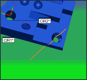
If the beam is within range, it appears in the Graphic Display window and blinks whenever the laser beam pulses. As the beam move toward the part, the indicator begins to change colors. As it nears the desired focal range, it changes colors from red, to orange, then yellow, then yellow-green, and finally to green.

A sample scan-line indicator (in orange) shows that the beam's scan-line position is too far above the part
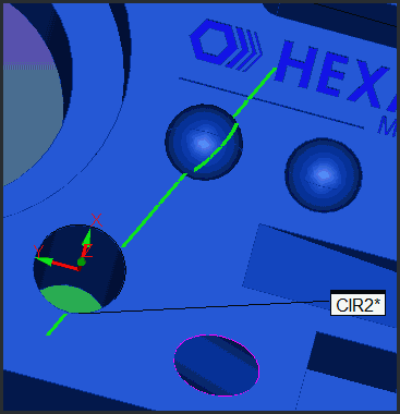
This green color signifies that the beam is at the optimal distance away from the part for scanning.

A sample scan-line indicator (in green) shows that the beam's scan-line position is at the optimal focal distance
If you move the beam too close to the part, it again moves away from the desired green color and toward a red color.