Select the Magnification
tab  , and adjust
the magnification until you decrease it to the minimum setting (zoomed
out).
, and adjust
the magnification until you decrease it to the minimum setting (zoomed
out).
The manual alignment in this example consists of an Arc and a Line. You can more accurately re-measure these datum features in "Step 3: Re-measure the Datum Features". Before you begin, mount the part so it is reasonably square to the axes of the measuring machine.
To measure the datum features, do the following:
Select the Magnification
tab , and adjust
the magnification until you decrease it to the minimum setting (zoomed
out).
With a manual (approximate) alignment, leaving the magnification at the minimum is acceptable and usually desirable, because it is easier to run the measurement routine. The DCC (refined) alignment will later improve the quality of these datum features.
Select the Illumination
tab  , and set
the Top Light to 0% (Off) and the Bottom Light to 35%.
, and set
the Top Light to 0% (Off) and the Bottom Light to 35%.
From the Auto
Feature toolbar, click Circle  to open
the Auto Feature (circle) dialog box.
to open
the Auto Feature (circle) dialog box.
Select the Vision tab.
Move the machine so the Arc (Datum B) is within the Field of View (FOV).
Click three points spaced along the edge of the arc. The software overlays a radial target on the arc as shown below:
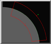
Click Create to add this circle to the measurement routine.
From
the drop-down list box of the Auto Feature
dialog box, select Line  .
.
Move the machine so the Edge (Datum C), adjacent to the previously measured arc, is within the FOV.
Click two points - One on the left end and one on the right end. The software overlays a line target on the edge as shown below:
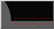
Click Create to add this line to the measurement routine.
Click Close to exit the Auto Feature dialog box.