Laser Clipping Region Properties tab
The Laser Clipping Region Properties tab allows you to set parameters to discard data outside a specified region, within the sensor's field of view. This feature lets you keep only pertinent data.
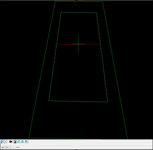
Keystone: The large green trapezoid in the Laser View (see below) represents the sensor’s maximum field of view. The clipping region is within this field of view.
Sensor Based Clipping region: The smaller green trapezoid within the sensor’s field of view.
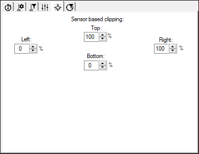
The Top, Left, Right, and Bottom boxes can be set with values from 0 to 100 percent that allow control over the clipping region. This lets you discard unnecessary data.
When the Bottom and Left values are at 0% and the Top and Right values are at 100%, the sensor keeps all of the data collected because the clipping region is the same as the maximum field of view.
Example of clipping data using Top 85, Bottom 85, Left 15, and Right 15
You can use the clipping region, for example, when measuring a hole. Since you wouldn’t want data from a neighboring hole to interfere with the feature computation, you can control the area that is clipped, thereby discarding the unwanted data.
Dragging Lines
You can also use your pointer and drag the clipping region lines of the smaller green trapezoid to set the desired percentage that way.
You must have an active Internet connection to see this video.
