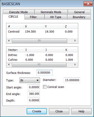
To scan a circle feature, select Insert | Scan | Circle. The CIRCLE tab in the BASICSCAN dialog box appears. For example:
BASICSCAN dialog box - CIRCLE tab
This tab takes parameters such as the circle's center and diameter and enables the CMM to execute the scan.
The circle method:
Enables use of the DISTANCE or NULLFILTER type on the Filter tab.
Enables use of only the VECTOR type on the Hit Type tab.
Does not need a boundary condition set on the Boundary tab.
The Centroid parameter in the # column is the center of the circle. You can directly type the center of the circle. Or, it can be obtained from the machine or CAD.
Defining a Circle Basic Scan
You can define a circle basic scan in one of these ways:
Directly type the values. See "Circle Basic Scan - Type Values Method".
Physically measure the points on the circle. See "Circle Basic Scan - Measured Point Method".
Click on the circle in the CAD model in the Graphic Display window. See "Circle Basic Scan - Surface Data Method" or "Circle Basic Scan - Wireframe Data Method".
Once you create the scan, PC-DMIS inserts it into the Edit window. Following is an example of a command line for a circle basic scan in the Edit window:
SCN2 =BASICSCAN/CIRCLE,NUMBER OF HITS=80,SHOW HITS=NO,SHOWALLPARAMS=YES
    <25.399,76.2,0>,CutVec=0,0,1,IN
    InitVec=-1,0,0,DIAM=25.4,ANG=0,ANG=360,DEPTH=0,THICKNESS=0,CCE=NO,
    PROBECOMP=YES,AVOIDANCE MOVE=NO,DISTANCE=0
    FILTER/DISTANCE,1
    EXEC MODE=FEATURE,USEHSSDAT=YES,USEDELAYPNTS=NO
    BOUNDARY/
    HITTYPE/VECTOR
    NOMS MODE=MASTER
    ENDSCAN
General Definitions for Basic Circle Scan
Centroid: Center of the circle.
CutVec: Defines the plane in which the circle lies.
InitVec: The surface normal vector of the point the scan defines as 0 degrees. The scan will start at this location plus the Start angle degrees. It can also be thought of as a zero angle vector.
The CutVec and InitVec are normal to each other.
More:
Circle Basic Scan - Type Values Method
Circle Basic Scan - Measured Point Method
Circle Basic Scan - Surface Data Method