
The Alignment tab on the Pattern Setup dialog box provides the basic options of pattern setup for non-curve patterns. It can also establish a temporary alignment for an angle offset pattern.
Offset
The X axis, Y axis, and Z axis boxes allow you to set the X, Y, and Z Offsets between pattern occurrences. PC-DMIS offsets the nominal X, Y, and Z data of the pasted feature (or set of features) by these offset values.
The Angle box allows you to set the angular offset between pattern occurrences.
An angular offset may be useful when you measure the position location of several holes in a bolt hole pattern where the datum is a hole in the center of the pattern. PC-DMIS rotates the offset around the origin defined with the Center of Rotation area.
You can use angular offsets with X, Y, and Z offsets and the flips in the Mirror area. PC-DMIS applies these offsets in this order: flips, rotations, translations.
Mirror
This allows you to mirror an axis. The Flip X, Flip Y, or Flip Z option flips the selected X, Y, or Z axis for the pasted pattern. No Flip means the axis is not flipped.
Center of Rotation
The Center of Rotation area contains boxes for you to define a rotation center for an angle offset pattern (for example, a bolt hole pattern around a central hole). Prior to version 2021.1, if you wanted to do an angle pattern around a central hole, you had to create an alignment at that feature. Now, you don't have to create that alignment. Instead, you can click on the central circle feature, and PC-DMIS extracts the XYZ center location from the CAD and puts those values into X center, Y center, and Z center boxes. PC-DMIS applies the rotation around the center of rotation and within the currently active workplane.
This box becomes available to edit, if you type a value in the Angle box under Offset.
Number of times to offset
This box lets you set the number of times that PC-DMIS offsets a pattern. The default value is 1.
Use default prefix
The Use default prefix check box specifies whether PC-DMIS uses a default ID prefix when you use the Paste With Pattern menu item to paste features.
If you select this check box, the Paste With Pattern menu item uses the default ID prefix when you paste new features.
If you clear this check box, the Paste With Pattern menu item uses each feature ID as the base feature name and adds an incremental and numerical suffix.
If you don't use a default prefix when you paste many lines, the processing time is longer because each feature ID represents a new pattern.
Flip Feature Order
The Flip Feature Order check box reverses the order of the pasted features.
This check box works only with Auto features and measured features. Also, this works with only these move commands:
MOVE/POINT,MOVE/INCREMENT,MOVE/CLEARPLANE,MOVE/CIRCULAR,MOVE/ALL,and MOVE/CLEARPOINT
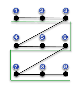
Suppose you have three Auto features: 1, 2, and 3. If you don’t select this check box, PC-DMIS pastes the new features as 4, 5, 6.
If you select this check box and change the Number of times to offset value from 1 to 2, you have nine features in this order: 1, 2, 3, 6, 5, 4, 7, 8, 9. Each new set of features (6, 5, 4 and 7, 8, and 9) reverses its order from the previous set. PC-DMIS follows that order during execution. In the diagram below, you can see this with the green lines. If you don't select this check box, the black lines show the original execution order:
Apply "Paste With Pattern" on OK
You can manually select the Paste With Pattern menu option if you like, or you can use this check box. This check box applies the Paste With Pattern operation behind the scenes automatically when you click OK.
More: