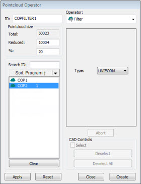
Pointcloud Operator dialog box - Filter Operator
The Filter operation filters data to a smaller subset of points.
To apply the Filter operation to a pointcloud, on the
Pointcloud toolbar, click Filter
Pointcloud ( ), or select Operation
| Pointcloud | Filter.
), or select Operation
| Pointcloud | Filter.
The Filter operator has these options:
Type - Indicates the type of filter operator to apply:
UNIFORM - This option generates a subset of points distributed evenly in the X, Y, and Z directions. It produces the same effect as a regular grid in 2D, but in this case the effect is a 3D grid.
CURVATURE - This option generates a subset of points with the highest estimated curvatures, mainly around edges, vertices, and highly curved areas of the surface.
RANDOM - This option generates a subset of points randomly distributed in the pointcloud.
DISTANCE - This option generates a subset of points where points are at least the specified Distance value apart from each other.
Distance - When you select DISTANCE, the value you enter in this box specifies the distance for the distance filter.
INCIDENCE ANGLE - This option generates a subset of points which excludes (filters out) points that have a normal vector orientation that fall outside the specified angle, relative to the laser sensor orientation. This filter allows you to remove laser points caused by secondary reflections or "noise". You can see the effect of this filter after you click the Apply button in the dialog box.
A valid value is any real number from 10 to 90, inclusive.
To use this filter, the pointcloud data must have vector information.
NOISE REDUCTION - The Noise Reduction filter works on the global density of the selected pointcloud. PC-DMIS removes the points that are too far away from the global density of the pointcloud.
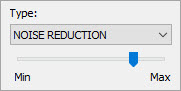
The slider represents the minimum and maximum values for the Noise Reduction filter. The Min value represents 0 (zero). Zero means the software applies no noise filter to the data. The Max value represents the highest value you can set the noise filter to. The highest value is 99. The default value is 80, and that is where the slider is set to in the above image.
As you move the slider, PC-DMIS updates the display in the Graphic Display window to show the excluded points in red. The software keeps the included points in green.
To filter COP data:
From the Type list, select a filter type.
From the list of commands, select the Pointcloud command to which you want to apply the filter.
In the Reduced or % boxes, specify the number of points or the percentage of points to keep after applying the filter. This does not apply to the Distance filter.
Click the Apply button.
PC-DMIS filters the data, and the Graphic Display window shows the result. The size of the filtered data may differ slightly from the value that you specified. It is even more noticeable when you execute the measurement routine, and the software collects the data from the scan commands. It is generally impossible to get the same number of points from a laser sensor if you repeatedly scan the same entity.
When the results are acceptable, click the Create button. PC-DMIS adds a COP/OPER,FILTER command to the measurement routine that contains all the information related to the applied filter.
Suppose your COP1 had 10,000 points initially, and you have this COP/OPER,FILTER command in the Edit window:
COPFILTER3=COP/OPER,FILTER,UNIFORM,SIZE=3000
REF,COP1,,
The filter replaces the 10,000 points held in COP1 with the filtered 3,000 points. COP1 then holds the filtered 3,000 points for its pointcloud.