There two groups of data which must be supplied to ENC7480 when GMServer.exe tries to communicate with it. These data groups are "CMM Options" and "TCP Communication Options". See below for the description of all the options and an example of the GMICONFIGDATA.XML file.
CMM Options
StartupEXE = GMServer.exe - When configured, GMServer starts and terminates automatically after ManualCMM.dll initializes and closes.
AxisX = 0, AxisY = 2, AxisZ = 4 - These parameters define the X, Y, and Z orientation coordinates from the encoder. The default values are 0, 2, 4 which correspond to the X (back to front), Y (left to right), and Z (down to up) orientations.
Transport = TCP - Defines the method of connection to GMServer.exe which uses TCP. See "TCP Communication Options" below.
RequestInterval = 100 - Defines the number of milliseconds between data updates.
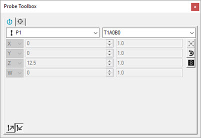
ReadoutButton = False - Set to True for systems that cannot take manual hits and provide scale readouts simultaneously. This entry requires that you select either Readouts mode or TakeHits mode.
When set to True, PC-DMIS displays a pair of user interface buttons on the Position Probe tab of the Probe Toolbox. These buttons allow you to toggle between these two modes.
Probe Toolbox Position Probe tab showing buttons when ReadoutButton = True
XYZReverseVector = False - Set this parameter to True to reverse the direction of the vectors read or calculated by the parser.
ScaleX = 1.0 - This value specifies the scale factor for the X axis. Change this value to accommodate any scale stretch.
ScaleY = 1.0 - This value specifies the scale factor for the Y axis. Change this value to accommodate any scale stretch.
ScaleZ = 1.0 - This value specifies the scale factor for the Z axis. Change this value to accommodate any scale stretch.
WScale - This value specifies the scale factor for the rotary table's W axis. Change the value to accommodate any scale stretch.
The default value for ScaleX, ScaleY, ScaleZ and WScale is 1.0.
HasJogbox = False - This parameter is not implemented.
HasRotaryTable = False - This parameter is not implemented.
AutoResetCounters = False - Automatically resets the counters when set to True.
CMMAddress_IP = localhost - This parameter defines the IP address of CMM/GMServer.exe. It allows running PC-DMIS on a different machine that the GMServer is executed from and communicates with the CMM.
CMMPort_IP = 1390 - This parameter defines the TCP port the CMM/GMServer listens to for incoming requests to establish communication with PC-DMIS.
Example for GMServer running ENC7480 or GmsSimulator:
<GMIConfig>
<Misc cmm="Enc7480">
<Data>
<AxisX>0</AxisX>
<AxisY>2</AxisY>
<AxisZ>4</AxisZ>
<HasJogbox>false</HasJogbox>
<HasRotaryTable>false</HasRotaryTable>
<ReadoutButton>false</ReadoutButton>
<RequestInterval>100</RequestInterval>
<ReverseIJKVector>false</ReverseIJKVector>
<StartEXE>GMServer.exe</StartEXE>
<Transport>TCP</Transport>
<XScale>1.0</XScale>
<YScale>1.0</YScale>
<ZScale>1.0</ZScale>
<WScale>1.0</WScale>
</Data>
</Misc>
<CommInfo>
<TCP>
<CMMAddress-IP>localhost</CMMAddress-IP>
<CMMPort-IP>1390</CMMPort-IP>
</TCP>
</CommInfo>
<Replies>
<HitReply>
<Reply>"\n ( %lf %lf %lf %lf %lf %lf %lf ) %3c\r"</Reply>
<Terminator>13</Terminator>
<IsBinary>false</IsBinary>
<MultiRecordReplies>false</MultiRecordReplies>
</HitReply>
<PositionReply>
<Reply>"\n ( %lf %lf %lf %lf ) %3c\r"</Reply>
<Terminator>13</Terminator>
<IsBinary>false</IsBinary>
<MultiRecordReplies>false</MultiRecordReplies>
</PositionReply>
</Replies>
</GMIConfig>
ManualCMM.dll Version 1.21 adds volumetric compensation
Added the corresponding standard options:
VolCompMethod = 0
ARM2CompMode = False
WCompensMode = 1
UsingOldWcompens32 = False
VolDebug = False
CompensFileName = compens.dat
VolOffset? = 0.0
ManualCMM.dll rotary table support
Added the ability for GMServer.exe to return seven floating point numbers (XYZ W IJK) for hits, and four floating point numbers for the position (XYZ W).
Added W_COUNTS_PER_TURN to GMSENC7480.XML.
Added the ability of ManualCMM.dll to scale the result with WScale from configuration file GMICONFIGDATA.XML. It then normalizes it to the interval from 360 to 360 degrees. If necessary, after normalizing completes, the interval changes from 0 (zero) to 360 degrees which is how PC-DMIS expects it.
Implemented W_COUNTS_PER_TURN to determine the resolution of the rotary table. For example, set this to 1, turn the rotary table 20 full times, divide the resulting number of ticks (or W_COUNTS) by 20. The result is then entered back into the W_COUNTS_PER_TURN parameter as the actual resolution of the rotary table.
Implemented the ability to use the Demo application enclosed with ENC7480 (ENC7480.exe) for the same purpose.
Updated the information about W (rotary table angle) from full turns to degrees. The values are positive or negative to distinguish clockwise and counterclockwise rotation. ManualCMM changes the value internally to be in the interval from 0 to 360 which is required by PC-DMIS.
Interrupts for PC-DMIS buttons (PCD buttons).
ManualCMM supports the following button configurations which GMServer can then receive:
<BUTTONS>
<Button line=”num”>"pcd_button"</Button>
</BUTTONS>
num - The valid values are 0 to 32 inclusive, meaning X2 and X3 are the connector's digital input line.
pcd_button - The valid values are:
PCDMIS_BUTTON_DONE (0)
PCDMIS_BUTTON_ERASE (1)
PCDMIS_BUTTON_MOVEPOINT (2)
PCDMIS_BUTTON_STOP (3)
PCDMIS_BUTTON_CONTINUE (4)
The GMServer on the ENC7480 checks the X2 and X3 connectors on 16 input lines for change from 0 to 1 (low to high). For more information, see the "function Enc7480_Read_InPort" description in the “User’s Manual for the ENC7480”. You can find this on the manufacturer’s website (http://www.leadshine.com).
This check happens in intervals of POLL_TIME. For details, see "Generic Machine Server (GMServer.exe)".
When two changes happen at the same time on two lines, GMServer uses the lower.
Every line can be configured in ENC7480.XML to send certain PC-DMIS button commands.
ManualCMM receives this message from GMServer found in the debug file:
“PCD_BUTTON:<num>"
BUTTONS_NEGATIVE_POLARITY - Allows you to switch from negative polarity (True - default) and positive (False).
BUTTONS_DEBOUNCE_LEVEL - Provides software detection for de-bouncing. This is a multiple of POLL_TIME and represents a time for which “1” has to be kept so click would be accepted.
Example:
<BUTTONS>
<Button line="0">PCDMIS_BUTTON_DONE</Button>
<Button line="2">PCDMIS_BUTTON_ERASE</Button>
<Button line="3">PCDMIS_BUTTON_MOVEPOINT</Button>
<Button line="4">PCDMIS_BUTTON_STOP</Button>
<Button line="5">PCDMIS_BUTTON_DONE</Button>
<Button line="15">PCDMIS_BUTTON_CONTINUE</Button>
</BUTTONS>
<BUTTONS_DEBOUNCE_LEVEL>1</BUTTONS_DEBOUNCE_LEVEL>
<BUTTONS_NEGATIVE_POLARITY>true</BUTTONS_NEGATIVE_POLARITY>
When multiple instances of an item is listed, as in the PCDMIS_BUTTON_DONE item that appears twice in the above example, the last instance (line 5 in the above example) is used.
When you allow monitoring in GMServer, the window shows the PCD button click information: PCD_BUTTON:0 for PCDMIS_BUTTON_DONE.
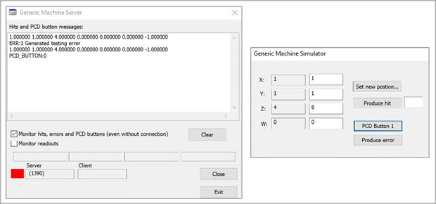
Example of PCD button click with simulator
Debugging capability
GMS.XML has to contain the DEBUG definition. For details, see the "Configuration of the GMServer- GMS.XML" section of the "Generic Machine Server (GMServer.exe)" topic in this document.
The debug file captures the information about the version of GMServer.exe and then calls to these digital I/O functions are tracked down: Enc7480_Read_InPort Enc_Read_OutPort. When the output from those functions change, GMServer writes the new state of the digital I/O into the debug file.
Example of debug file:
GMServer ver: 1,0,31,0
Enc7480_Read_InPort: 0xFFFFFFFF
Enc7480_Read_OutPort: 0x0