PC-DMIS can highlight Auto features during both routine creation and execution. PC-DMIS can also automatically scale and rotate to the Auto features during execution in the Graphic Display window. These abilities provide a better user experience when you create and execute a measurement routine with a portable device.
Feature Highlighting During Creation
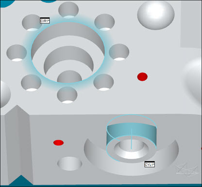
When you create an Auto feature, PC-DMIS draws the outline of the Auto feature in the Graphic Display window in a blue outline color. PC-DMIS also highlights the current feature once you select the feature in the Edit window.
If it's a 2D feature, such as a circle, PC-DMIS gives the feature outline a glow in the highlight color.
If it's a feature that has a surface, such as a cylinder, PC-DMIS draw the surface in the highlight color, but there is no glow.
The example below shows two highlighted (or selected) features, a circle on the top surface, and a cylinder on the front surface:

Feature Highlighting During Execution
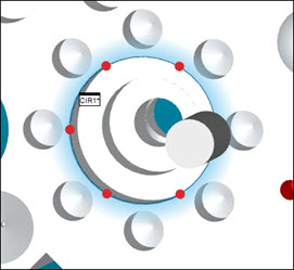
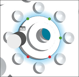
After an alignment command, if you execute any manual feature, PC-DMIS rotates and zooms the part to show the manual feature in a slightly isometric view. It also highlights the feature, and shows the expected nominal points to measure that feature as red spheres. The red spheres help you know the general location of where to probe the points. As you take hits with the probe to measure the expected points, those spheres turn green in the Graphic Display window.
The images below show the above circle feature, with nominal points in red as execution begins. These turn to green as they are measured:
For the rotation and scaling to function, you must have a part alignment before the manual features.
Probe Trigger Highlighting
You can set up PC-DMIS to automatically take hits when the probe passes through a plane or moves within a radius of a feature. To set up probe triggers, see "Probe Trigger Options".
When your measurement routine contains trigger commands, PC-DMIS highlights those trigger areas in the Graphic Display window.
For example, in the Edit window, suppose you have a PLANE AUTOTRIGGER command above a circle feature (CIR1). During execution, PC-DMIS highlights the usually invisible trigger plane in green so that you can see where it is. When the probe passes through this plane, the probe records a hit:
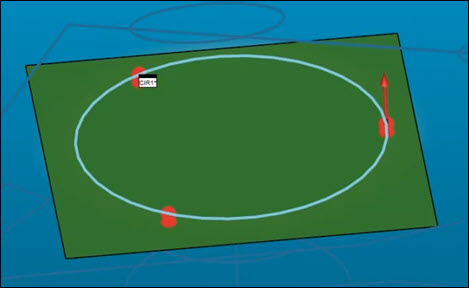
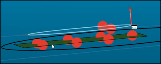
Here's another example that shows the probe trigger plane for an ellipse. Notice how the trigger plane bisects the nominal points:
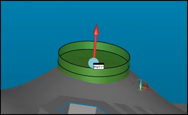
Here's an example that shows the trigger zone for a point from a POINT AUTOTRIGGER command. When the probe enters this zone, it registers a hit:
To see the trigger areas, you must have a part alignment before the manual features.
Configuring your Settings
If you don't see the above behavior, check these settings:
Access the Setup Options dialog box (Edit | Preferences | Setup).
From the General tab, mark the Auto scale manual feature during execution check box.
Click OK to save your changes and close the dialog box.
Access the Symbols tab on the CAD and Graphic Setup dialog box (Edit | Graphic Display Window | Display Symbols).
From the Point symbol area, set the list to Feature Point. Also, choose Sphere.
From the Sphere Attributes area, mark the Shaded and High Quality check boxes.
Click OK to save your changes and close the dialog box.